Greater Wellington Regional Council
Bus Services Equipment Operations
Manual- Part A
December 2018
Document History
Version
Issue Date
Changes
Issued to
Author
1
30 Sept
RFT release version
RFT release
Ai-Bee Tan
2016
1.1
21/4/2017 Update of ticketing-related Ai-Bee Tan; David Lewry;
Eamon Sweeney
content
David Dale;
1.2
10/5/2017 Minor updates to Ticketing A-Bee Tan; David Lewry;
Eamon Sweeney
Equipment content lists
Added draft Ticketing
Equipment Maintenance
and support protocol
1.2
8/6/2017 N/A
Operators
Ai-Bee
1.3
14/5/2018 Split into Part A and Part B
Patrick Farrell
Part B in separate
document
1.4 31/10/2018 Minor updates, plus
Amy Helm
inclusion of revised
provisions for reporting of
faults
1.5
10/12/18 Minor grammatical
Operators
Matthew Lear/
updates
Salsabil Elmegreisi
link to page 2 link to page 5 link to page 7 link to page 7 link to page 7 link to page 7 link to page 8 link to page 8 link to page 8 link to page 9 link to page 9 link to page 9 link to page 10 link to page 10 link to page 10 link to page 10 link to page 10 link to page 11 link to page 11 link to page 11 link to page 12 link to page 12 link to page 12 link to page 12 link to page 13 link to page 13 link to page 13 link to page 13 link to page 13 link to page 13 link to page 14
Contents
Contents
Document History ................................................................................................................................... 2
Glossary ................................................................................................................................................... 5
1
The purpose of this document .................................................................................................... 7
2
Document outline ....................................................................................................................... 7
Part A ............................................................................................................................................... 7
Part B ............................................................................................................................................... 7
Part A....................................................................................................................................................... 8
3
Real Time Information and Ticketing System description .......................................................... 8
4
Components of the RTPI and Ticketing Systems ......................................................................... 8
5
On-Board Equipment .................................................................................................................. 9
RTPI System components ................................................................................................................ 9
Ticketing On-Board Equipment ....................................................................................................... 9
Installation Kit expectations.......................................................................................................... 10
6
Applications ............................................................................................................................... 10
RTPI Applications .......................................................................................................................... 10
Ticketing Applications ................................................................................................................... 10
7
Operator-supplied components ................................................................................................ 10
8
De-installation or transfer of Equipment .................................................................................. 11
Operational Guide for Drivers ............................................................................................................... 11
9
Summary of data entry requirements ...................................................................................... 11
10
Pre-departure checks, signing on, and start of trip .............................................................. 12
Pre-departure checks .................................................................................................................... 12
11
GPS issues during trip............................................................................................................ 12
12
Printer paper replacement ................................................................................................... 12
13
End of trip and end of shift ................................................................................................... 13
14
Summary of Incident / Breakdown or Handover instructions .............................................. 13
Driver change mid-shift ................................................................................................................. 13
Leaving the bus ............................................................................................................................. 13
Transferring passengers between buses in cases of bus breakdown ........................................... 13
Vehicle change .............................................................................................................................. 13
Faults and repairs – instructions for Depot staff .................................................................................. 14
link to page 14 link to page 14 link to page 16 link to page 17 link to page 17 link to page 17 link to page 18 link to page 18 link to page 18
15
Faults diagnosis by drivers .................................................................................................... 14
16
Fault diagnosis by Depot staff ............................................................................................... 14
Table 1 - LED status indications .................................................................................................... 16
17
Reporting of faults by Depot staff ......................................................................................... 17
Faults, damage and repairs to RPTI System .................................................................................. 17
Faults, damage and repairs to the On-board ticketing equipment .............................................. 17
Inspection, cleaning and maintenance ................................................................................................. 18
18
Access for maintenance and repairs ..................................................................................... 18
19
Inspection, cleaning and maintenance by the Operator ...................................................... 18
Glossary
Application means software or a web-based programme used by the Operator’s operational
support staff to interact with the RTPI or Ticketing Systems.
Automatic Vehicle Location (AVL) Unit means the electronic device that comprises the
RTPI On-Board Equipment. Also known as
DT Unit
Bus Driver Console (BDC) which is a Ticketing On-Board Equipment component that is
used by bus drivers to log into and interact with the Ticketing System and other on board
Ticketing Equipment. It allows them to process payments for cash fares and record journey
events such as concessionary travel. The BDC communicates specific journey activity to the
RTPI System.
Bus Ticketing Driver User Manual (BTDUM) means the training manual provided by
Snapper to the Operators that describes how drivers are expected to interact with the
Ticketing Systems on-board equipment.
Depot Equipment means the RTPI or Ticketing System components installed at a Depot.
Equipment means the equipment provided by GWRC under the Partnering Contract, for the
purposes of Vehicle tracking, real time passenger information and ticketing systems
GPRS means ‘general packet radio service’. It is a packet oriented mobile data service on the
2G and 3G cellular communication system's global system for mobile communications
(GSM)
GPS means ‘global positioning services’. This is a space-based satellite navigation system
that provides location and time information in all weather, anywhere on or near the Earth,
where there is an unobstructed line of sight to four or more global positioning services
satellites
Horizon means Vix Horizon which is RTPI System software application that allows the
Operator to interface with the RTPI System’s operational support and passenger information
functionalities.
Interface means a shared boundary across which two separate components of a computer
system exchange information
On-Board Equipment means the RTPI or Ticketing System components installed on a
Vehicle.
Operator means the contracted provider of Passenger Operating Services in the Wellington
region
Operator Reports means the Vix RTPI System software which allows the Operator to
interface with the RTPI System’s data warehouse and reporting functionality.
Partnering Contract means the contract between GWRC and the Operator for the provision
of bus services under the Public Transport Operating Model framework
RTPI Equipment means all real time information equipment licensed to the Operator under
a Partnering Contract that is either installed in a Vehicle or held at the Operator's premises
RTPI System means the real time passenger information system supplied by the supplier, in
line with the Supply Agreement. Also known as
RTI System
Snapper BDC (bus driver console) means the Ticketing On-Board Equipment unit which
includes the touch screen interface to issue paper tickets for cash payment and to monitor the
status of the bus validators installed on-board. Also be referred to as the
ETM (Electronic
Ticketing Machine)
Software means the software forming part of the RTPI or Ticketing System/s to enable the
system/s to operate in line with the specifications set out in the Supply Agreement or as
directed by GWRC
Supervisor means whoever the driver needs to report to in any given situation e.g., the
manager, shift or duty supervisor, shift engineer, workshop staff person, cashier etc.
Supplier means the provider of relevant equipment to GWRC in line with a Supply
Agreement, and includes the Supplier’s subcontractors
Thermal Printer means the Ticketing On-Board Equipment component that is used to print
paper tickets for customers. It is also used to generate other paper-based outputs in relation to
the Ticketing System data and information.
Trip Off (or
Tripped Off) means the action of using the BDC to transmit information to the
Ticketing System indicating that a trip that the Ticketing System was Tripped On to, has
stopped being delivered.
Trip On (or
Tripped On) means the action of using the BDC to transmit information to the
Ticketing System indicating that a specific trip in the schedule is currently being delivered.
Validator means the Ticketing On-Board Equipment component that is used to validate
transactions made using eligible electronic media (e.g. a smartcard) and debit the fare. Also
known as the
Snapper Card Reader or
Fare Payment Device (FPD) in some materials.
Vehicle means a vehicle used by the Operator to provide Passenger Operating Services in the
Wellington region
Note: Defined terms in the Partnering Contract have the same meaning where used in this
document.
1
The purpose of this document
1.1
The Bus Services Equipment Operations Manual (BSEOM) provides instructions
about how to manage and use the components of GWRC’s Real Time Passenger
Information (RTPI) and Ticketing Systems made available to the Operator.
1.2
It is intended to work as a supporting document, providing detail about how to use
the equipment components of those systems to meet contractual obligations,
without duplicating information already included in the Partnering Contract or other
manuals.
1.3
The BSEOM will be updated from time to time to ensure it remains fit for purpose.
2
Document outline
2.1
The BSEOM is formed of two parts.
Part A
2.2
This part focuses on the on-bus equipment components that the drivers will interact
with. The sections of
Part A include:
2.3
RTPI and Ticketing Systems Description: This section lists the on-board equipment
components that the driver will manage or use, as well as the applications that
operate in the backend of that equipment.
2.4
Operational Guide for Drivers: This section is supporting information for drivers
with regard to the on-board equipment. This part is able to be detached from the
BSEOM and issued to bus drivers as a stand-alone document to describe key
activities that drivers undertake.
2.5
Faults and repairs – instructions for Depot staff: This section describes the
procedures for reporting faults to GWRC and its contractors.
2.6
Inspections, cleaning and maintenance. This section outlines expectations regarding
inspections, cleaning and maintenance.
Part B
2.7
This part focuses on the back-end systems and applications that enable the RTPI
and Ticketing Systems provided by GWRC and used by Operators. The sections of
Part B include:
2.8
Overview: This section outlines the GWRC owned systems (Resolve, PTWFS and
PTBIS) that the Operator will manage or use.
2.9
Applications and Software systems: This section describes the functions of the
background technology systems that the Operator will interact with and the
information requirements that the Operator is expected to provide into those
systems.
2.10
Maintenance activities: This section describes the maintenance activities that are
the responsibility of Operators.
2.11
Part B is currently getting drafted and will be distributed to Operators once
finalised.
Part A
3
Real Time Information and Ticketing System description
3.1
The
Real Time Passenger Information (RTPI) System tracks all vehicles on the
GWRC/Metlink Network in real time, provides customers with real time predictions
of vehicle departure/arrival times, and provides the Operator and GWRC with real
time predictions of departure times, vehicle location information and other RTPI
data.
3.2
RTPI equipment on-board vehicles provide communication, tracking and data
logging functions for operational systems, and GPS tracking capability for the RTPI
System. This GPS data is provided in real time to the RTPI System via a web
service interface.
3.3
Data captured by the RTPI System about trip performance is also used to assess
performance against PTOM contractual Key Performance Indicators (KPIs).
3.4
The
Ticketing System is used to collect farebox revenue on Metlink bus services. It
is also used to tell the RTPI System which trip a driver is delivering. This
information is used by the RTPI System to support effective tracking of Vehicles
and accuracy of RTPI signs.
4
Components of the RTPI and Ticketing Systems
4.1
The components of the RTPI and Ticketing Systems made available to the Operator
by GWRC are split into two categories:
On-Board Equipment, which is the physical equipment installed on the vehicles
Applications, which is the software enabling functioning of the RTPI and
Ticketing Systems.
4.2
There is currently no Depot equipment although GWRC reserves the right to
require Depot equipment to be installed. GWRC will give reasonable notice and
work with the affected Operator if the need arises.
 5
On-Board Equipment
RTPI System components
5
On-Board Equipment
RTPI System components
5.1
RTPI On-Board Equipment includes:
Automatic Vehicle Location (AVL) Unit, comprising a DT421 On Vehicle
Computer (or equivalent) and a DT470 Driver Display (seen in pictures above)
– it can also be referred to as a DT Unit
RTPI On-Board Equipment Installation Kit, consisting of:
o
Antenna
o
Wiring
o
Driver Display mounting bracket
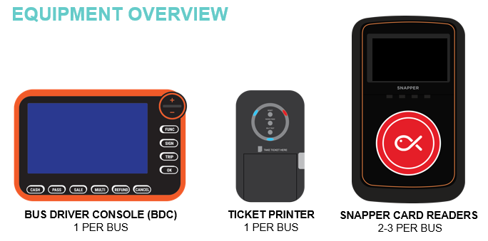
Ticketing On-Board Equipment
5.2
Ticketing On-Board Equipment includes:
Snapper Bus Driver Console (BDC)
Ticket Printer (Thermal Printer)
Validator (also called Snapper Card Reader or Fare Payment Devices (FPD))
Ticketing On-Board Equipment Installation Kit, consisting of:
o
Cable looms
o
Switched-mode Power Supply (SMPS)
o
GPS antenna
BDC mounting bracket
Thermal printer mounting bracket
Leaner/grabber bracket
Installation Kit expectations
5.3
The Installation Kit is installed by bus builders if being installed on a new build
bus.
5.4
The Installation Kit is installed by the Equipment Supplier, if being installed in an
existing bus.
5.5
All other On-Board Equipment is installed by the Equipment Supplier at the time of
bus commissioning.
6
Applications
6.1
Applications will be further detailed in
Part B of this document
RTPI Applications
6.2
RTPI Applications consist of:
Vix Horizon
Operator Reports
Ticketing Applications
6.3
Ticketing Applications consist of:
Snapper Operator Reporting Portal
Snapper Service Desk tool
7
Operator-supplied components
7.1
Operator-supplied components consist of:
A PC or other device, with the following capabilities:
o
Operating System: Windows 7 or above
o
broadband internet connection
o
internet browsing software (currently Internet Explorer 11.0 or newer) that
is compatible with RTPI Applications and Ticketing Applications
o
security settings that allow the computer or device to access RTPI
Applications and Ticketing Applications
o
a suitable permanent power supply
Note: A dedicated computer or device is not required.
Thermal printer paper for Ticketing On-Board Equipment Thermal Printer, with
the following specifications:
o
Type: Thermal transfer paper
o
Width: 57mm
o
Maximum Length: 50 metres
8
De-installation or transfer of Equipment
8.1
In no circumstances should the Operator de-install or transfer the RPTI Equipment.
If the Vehicle is leaving the fleet, the Operator must:
notify their GWRC Account Manager
log a service request through Metlink Systems for the RTPI Equipment to be de-
installed
log a service request through the GTA portal for the Ticketing Equipment to be
de-installed.
8.2
For transferring Ticketing Equipment the Workshop Team should follow the
procedure for swap-outs manual.
8.3
All On-Board Equipment must be de-installed before the Vehicle leaves the fleet.
Operational Guide for Drivers
Handle with care
RPTI Equipment and Ticketing Equipment must be handled with care. While you may
adjust the positioning of displays, take care not stretch, pull or unplug any wires.
9
Summary of data entry requirements
9.1
More detail on the data entry requirements are in the Bus Ticketing Driver User
Manual (BTDUM) issued by Snapper. Refer to the BTDUM for all instructions on
how to use the Snapper BDC.
9.2
Drivers do not need to enter any data into the RTPI on-board AVL unit.
9.3
All data is entered on the Snapper BDC which is then used by the RTPI System.
9.4
Drivers MUST enter accurate data into the Snapper BDC at the correct time and
when the vehicle is at the correct location - the accuracy of the RTPI System is
(amongst other things) critically dependent on this action by all drivers.
10
Pre-departure checks, signing on, and start of trip
Pre-departure checks
10.1
The pre-departure checks are a quick check performed by the driver on the AVL
unit, Snapper BDC, and Snapper Card Reader before the vehicle starts its first
journey of the day OR when the vehicle or driver changes.
10.2
Any faults found must be reported immediately to the Depot Supervisor. The driver
should also report if any on-board equipment is damaged or missing.
10.3
The driver must check that the AVL unit:
Turns on when the vehicle starts
Boots up to the main interface screen
GPS and GPRS 4G cellular indicators both show signal
10.4
Instructions on how and when to SIGN ON and TRIP ON are provided in the
Snapper BTDUM.
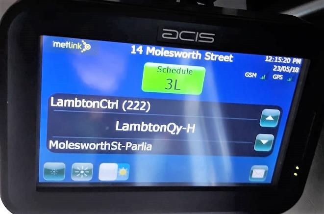
10.5
After ‘tripping on’ the driver is to ensure the AVL Unit displays the correct route
number, next stop, date & time, driver details, and punctuality information
10.6
If the AVL does not turn on and boot up, or any information on the AVL Unit is
incorrect, or does not match what appears on the BDC, drivers should follow the
RTI On Board Equipment 1st Level Fault Diagnosis Check sheet. If the fault is not
resolved, the driver should report the fault to the Depot Supervisor immediately.
11
GPS issues during trip
11.1
If there is a problem with the GPS connection during the trip, then the driver may
need to move the BDC manually through the stops on the route. If the GPS signal
fails, arrows will appear and the driver can tap them to move the information on to
the next stop. Full instructions are provided in the BTDUM.
11.2
This is important as the fares will be calculated based on the stop information being
correct.
12
Printer paper replacement
12.1
The driver will monitor the Printer to ensure it contains paper to print tickets and
the paper is scrolling correctly. If it runs out of paper, the driver must put more
paper in the printer.
12.2
Instructions on interacting with the Printer can be found in the BTDUM.
13
End of trip and end of shift
13.1
Details on end of trip and end of shift procedures are provided in the BTDUM.
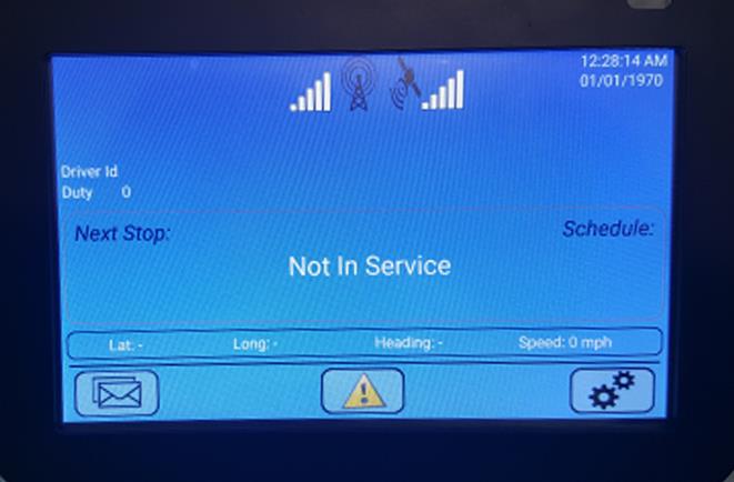
13.2
Always check that the AVL Unit shows
NOT IN SERVICE after tripping off.
13.3
The same process is followed if a relief driver comes to take over a route for any
reason.
14
Summary of Incident / Breakdown or Handover instructions
14.1
Details on the correct data entry steps to follow in the event of an incident, vehicle
breakdown, or driver handover are provided in the BTDUM.
14.2
If drivers do not adhere to these data entry requirements, service information for
passengers will be negatively affected. (i.e. vehicle won’t track or track correctly).
14.3
Instructions for diagnosing and handling faults on the Ticketing Systems on-board
equipment are provided in the BTDUM. Any unresolved faults should be reported
to the Depot Supervisor immediately.
Driver change mid-shift
14.4
Driver changes may occur mid-shift, either between scheduled service trips or
during a scheduled trip at a nominated bus stop.
14.5
Refer to BTDUM for instructions on how to interact with the Snapper BDC during
a mid-shift driver change.
Leaving the bus
14.6
If the driver has to leave the bus for whatever reason, then the ticketing equipment
must be locked first. Instructions on how to do this are provided in the BTDUM.
Transferring passengers between buses in cases of bus breakdown
14.7
Refer to BTDUM for instructions on how to interact with the Snapper BDC when
transferring passengers between buses.
Vehicle change
14.8
Vehicle changes may occur mid-shift, either between scheduled in-service trips, or
during a scheduled in-service trip in cases of a breakdown, etc.
14.9
Refer to BTDUM for instructions on how to interact with the Snapper BDC during
a vehicle change.
14.10
If the vehicle change occurs between scheduled in-service trips, the standard SIGN
ON and TRIP ON process is followed.
Faults and repairs – instructions for Depot staff
Services must not run without working RTPI Equipment or Ticketing Equipment
All faults must be reported immediately. If there is a fault with either the RTPI Equipment
or Ticketing Equipment you may finish the service you are on and run the next service for
that Vehicle (as long as attempts are made to fix the Ticketing Equipment between
services). Otherwise, the Vehicle must stay out of service until the RTPI Equipment or
Ticketing Equipment is working properly.
15
Faults diagnosis by drivers
15.1
Drivers must report all faults, damaged or lost on-board equipment to the Depot
Supervisor immediately. Before reporting the fault, damage or lost equipment to
GWRC or its contractors, Depot staff must ensure the driver has undertaken the
relevant diagnostic checks. This helps to ensure only genuine faults are reported for
repair to the Equipment Supplier.
15.2
Driver diagnostic checks:
AVL unit not working correctly – refer to the RTI On Board Equipment 1st
Level Fault Diagnosis Check sheet
On-board Ticketing Equipment not working correctly – refer to the
BTDUM.
16
Fault diagnosis by Depot staff
16.1
When a vehicle is not tracking on the Vix Horizon Application, additional checks
may be carried out by Depot staff. This requires accessing the DT421 On-Vehicle
Computer, fitted within a locker on the Vehicle.
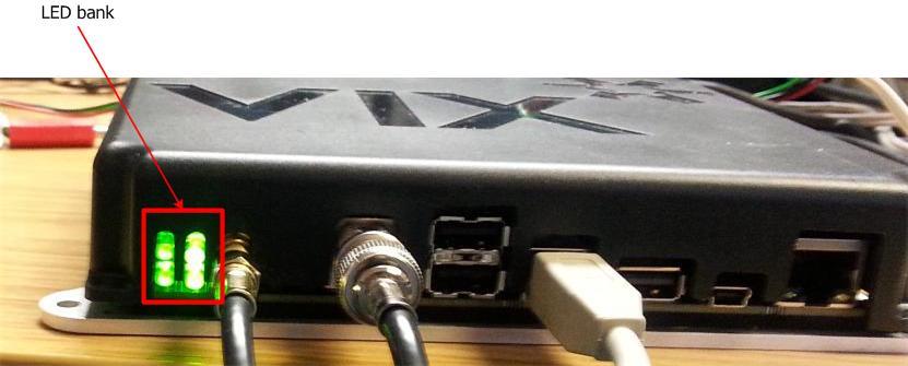
16.2
Check the LED pattern on the DT421 On-Vehicle Computer shows all four LED
lights are green. If not, refer to Table 1 below for analysis.
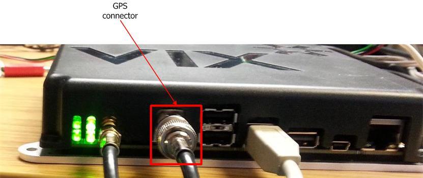
16.3
If a GPS fault is indicated, the Level 1 fault resolution process is to check if the
GPS cable (highlighted in red) is plugged in and screwed up tight.
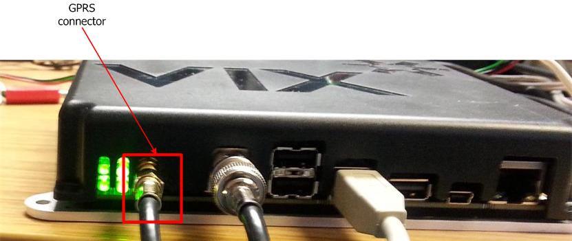


16.4
If a GPRS fault is indicated, the Level 1 fault resolution process is to check if the
GPRS cable (highlighted in red) is plugged in and screwed up tight.
Table 1 - LED status indications
Description
Graphical
Meaning
representation
All LEDs on constant green. Start
Normal operation.
sequence is complete and the DT421
On Vehicle Computer is on.
Bottom left LED on constant red, all
The DT421 On Vehicle Computer internal
other LEDs off.
fuse has blown.
Top left LED on constant red, bottom
The DT421 On Vehicle Computer has
left LED on constant green, other LEDs
started up with a low supply voltage (less
off.
than 7V).
The DT421 On Vehicle Computer stays in this
state until the supply voltage rises above
7.5V.
Top left LED on constant red, all other
At some point after start-up the DT421
LEDs off.
On Vehicle Computer supply voltage has
dropped below 7V.
The DT421 On Vehicle Computer stays in this
state until the supply voltage rises above
7.5V.
Bottom left LED flashes green slowly
Main power has been applied but the
(on 0.5s /off 2s).
vehicle master switch is off.
You can start the DT421 On Vehicle
Computer by switching the vehicle master
switch on.


 Description
Graphical
Meaning
representation
Description
Graphical
Meaning
representation
Top left LED on constant amber,
The vehicle master switch has been
bottom left LED flashes green fast
switched off and the DT421 On Vehicle
(50ms alternating), other LEDs off.
Computer is counting down a
preconfigured number of seconds before
switching off.
You can cancel this at any time during the
countdown by switching the vehicle master
switch on.
Top left LED slow flashing amber (on
The On Delay routine has been activated.
0.5s /off 2s), all other LEDs off.
The DT421 On Vehicle Computer is waiting
for a predefined number of seconds before a
normal switch on.
Top left LED gives a single amber 50ms
The internal system health check heartbeat
flash then returns to constant green,
is active.
bottom left LED on constant green.
Other LEDs irrelevant.
Top right LED on constant red, other
No GPRS coverage.
LEDs irrelevant.
Bottom right LED on constant red,
No GPS coverage.
other LEDs irrelevant.
17
Reporting of faults by Depot staff
17.1
All faults, damage or lost equipment must be reported immediately.
Faults, damage and repairs to RPTI System
17.2
If there is a fault with or damage to the RTPI on-board equipment, report the fault
via email to Metlink Systems following the process in Raising Support Calls. This
includes information on how to classify the fault and what information must be
supplied when reporting the fault.
17.3
If the RPTI Equipment is damaged, include high quality images of the damage in
the email. Also provide a brief report of the cause of the damage.
Faults, damage and repairs to the On-board ticketing equipment
17.4
If there is a fault with or damage to the On-board ticketing equipment, report the
fault to Snapper via the GTA Portal.
17.5
If the On-board ticketing equipment is damaged, Snapper’s contractors will take
high quality images of the damage and provide a brief report to Snapper on the
cause of the damage.
17.6
Operators may repair or replace some components of the On-board ticketing
equipment, as advised by Snapper. Operators must follow the instructions of
Snapper in carrying out this work, including any instructions regarding the return of
faulty equipment.
Inspection, cleaning and maintenance
18
Access for maintenance and repairs
18.1
To allow for maintenance and repair of the RPTI System as required, the Operator
and GWRC will mutually agree dates and times when GWRC (or its contractors)
will have access to Depots and relevant Vehicles at the Depots. If the relevant
Vehicles are not made available at the agreed times, the Operator may be charged a
call-out fee.
18.2
To allow for maintenance and repair of the Ticketing System the Operator will
report the request to Snapper via the GTA Portal.
19
Inspection, cleaning and maintenance by the Operator
19.1
Drivers are to conduct regular inspections and checks of the On-Board Equipment
as set out in section 10 of this manual. On-board Equipment should be maintained
to a reasonable standard of cleanliness, following any instructions for cleaning in
the Equipment Suppliers operating manuals.