Speed Detection Equipment Operators
Manual
Version 2013/01
Table of Contents
1.
About this manual .................................................................................................. 3
2.
Background ............................................................................................................. 4
3.
Radar speed detection ............................................................................................ 7
4.
Self‐paced test – Radar ......................................................................................... 16
5.
Laser speed detection ........................................................................................... 17
6.
Traffic laser ........................................................................................................... 21
7.
Self‐paced test – Laser .......................................................................................... 23
8.
Operating principals ............................................................................................. 24
9.
Evidential requirements ....................................................................................... 26
10.
Operating guidelines ‐ Radar ............................................................................ 27
11.
Operating guidelines ‐ Laser ............................................................................. 28
12.
Practical test requirements ‐ Radar .................................................................. 29
13.
Practical test requirements ‐ Laser ................................................................... 32
14.
Answers for self‐paced test – Radar ................................................................. 35
15.
Answers for self‐paced test – Laser .................................................................. 37
CODE OF OPERATIONS – SPEED DETECTION EQUIPMENT ........................................... 39
2
1.
About this manual
Goal
This manual is designed to provide the theoretical basis for the
safe and efficient operation of speed enforcement equipment.
Objectives
When you have completed this manual you will be able to:
identify the requirements of the Code of Operations
explain:
pre‐deployment testing
site selection
safety requirements
tracking history
outline the evidential requirements for speeding offences.
Manual Content
This manual contains the following sections:
background
radar speed detection
laser speed detection
operating guidelines
evidential requirements
practical training guide/check list
speed detection Code of Operations
Manual and operators manual
The manufacturer’s operational manuals for radar and laser
speed detection systems used by the NZ Police are
inappropriate for the New Zealand environment. For this
reason this manual and the New Zealand Operators Manual are
the only documents detailing the manner of operation New
Zealand operation.
Information
Should you have any questions or comments regarding this
manual please contact:
Inspector Mark Stables
Manager: Crash Investigation and Calibration Services
Police National Headquarters
Phone 04 494 9040 or Extn 42590
Version 2013/01
2.
Background
Introduction
Research has shown that speed is a major contributor to fatal
and injury‐causing road crashes. The Government has identified
increasing road safety as an important and core part of police
business. Significant improvements have been made in
enhancing road safety in the last few years. The aim of the NZ
Police is to ensure this trend continues by using a range of tools
including speed detection equipment.
Trained operators
For police members to use speed detection equipment they
must first be certified as a trained operator.
To become a certified operator you must:
have read and understood this manual
achieve a minimum of 80% in the theory test
undergo 20 hours’ practical instruction with a qualified
instructor who will assess your competence
be certified as a trained operator by the National Manager:
Road Policing (Police National Headquarters).
Twenty hours have been allocated for practical training. The
suggested breakdown of hours is 16 hours for radar training
and 4 hours for laser training.
Speed enforcement detection
The speed detection operators’ manual focuses on the use of
manual
speed detection equipment. It provides an overview of the
operating principles and policy guidelines governing the use of
speed detection equipment. Evidential and administrative
requirements are covered to ensure all operators are able to
follow correct procedure.
Within the manual there are two short tests. These are
designed so that you can measure your progress. Once you are
satisfied you understand the theory of operation of Police
speed detection equipment you must pass the associated
theory tests. A pass mark of 80% is required. The tests are
available on the Police Intranet via the Te Puna application.
Results will be recorded in PeopleSoft.
Practical
Once you have passed the test you will need to gain practical
experience operating the speed enforcement equipment. This
will take at least 20 hours and needs to be completed with a
qualified instructor. Your district Road Policing Manager has a
list of approved instructors.
The practical training is vital and provides an opportunity for
you to apply the theory in a practical setting. The qualified
instructors have a training checklist they will use with you to
guide your training and to assess your competence. A copy of
this checklist is at the end of the manual.
4
When you have completed the practical training and
demonstrated your competence in each area. Once satisfied
you are competent to operate the speed detection equipment
correctly
your
trainer
will
forward
the
necessary
correspondence to your Road Policing Manager for
certification.
Certified as a trained operator
Your Road Policing Manager will make the necessary
arrangements for your Certificate of Approval to be issued (via
Police Calibration Services). You will be issued a numbered
certificate and your details will be recorded on a national
database of trained operators.
Your instructor will issue you with a temporary approval to
operate speed detection equipment. This temporary approval
is valid until you receive your certificate from PNHQ.
If for any reason you require an additional copy of this
certificate you should contact Police Calibration Services
directly.
Manufacturer’s manual
While equipment manufacturer’s manuals are available off the
internet, these do not relate to the devices as used in New
Zealand. New Zealand police speed detection equipment has
different software designed specifically for New Zealand Police
which is not published or released to any other agency
internationally. The only manuals you may reference are those
published on the Police Intranet.
Code of Operations
In the interests of fairness, professionalism and accuracy the
Measurement Standards Laboratory New Zealand Limited and
the NZ Police have agreed to a Code of Operations that governs
the operation of all speed detection equipment used by NZ
Police. A copy of the Code of Operations 2001 contained in this
manual (2001 is still the current issue).
Using this manual
This manual focuses on both radar and laser speed detection
equipment. Radar and laser describe the scientific
methodology used to detect vehicle speed. Although there are
some similarities between the devices there are also some
fundamental differences. For this reason this manual looks at
each device separately. The first part of the manual deals with
radar and the second with laser. It is important that you note
the similarities and differences between the two types of
device.
Key information
The manual contains a reasonable amount of detail. This is to
provide depth to your understanding of how the devices
operate. You do not need to remember all the information
contained in the manual, however, there are some important
things that you must know. To help you identify the critical
information, the relevant sections are marked
key information
in the left‐hand column.
5
Self‐paced tests
Through the manual you will find two self‐paced tests. These
are available for you to test your own learning. The answers to
these tests are found at the end of the manual.
When you have finished the manual and feel you have
understood and can remember all the
key information material, you need to sit the assessment test.
Assessment test
The assessment test is available online via Te Puna. You need to
achieve a mark of at least 80% to pass the test.
6
3.
Radar speed detection
Introduction
Radar is an acronym for
RAdio
Detection
And
Ranging.
Radar means the transmission of radio waves that have the
ability to detect and provide the distance the object is away
from the transmission source.
History
The concept of radar was first discovered in 1904, but it was
during the Second World War that significant progress was
made in this area of research. New Zealand scientists who had
worked in this field during the war returned to work for the
Department of Science and Research and extended the
technology. The world’s first working traffic speed detection
radar was developed in New Zealand in the late 1940s. In 1947
the first traffic speed radar was trialled in Wellington. From
these humble beginnings radar devices have become an
integral part of the New Zealand road safety scene.
Although the models have changed and will continue to
change, the operating principles of radar devices remain the
same.
The use of radar as a speed enforcement tool is not restricted
to New Zealand. Radar speed detection devices are widely
used; each year over 50 million enforcement notices are issued
to speeding drivers around the world.
Use of radar
Radar is present in everyday life; when we make a telephone
call, use the internet or watch television the information is
carried, at least part of the way, by microwave. (Microwave is
the radio frequency at which radar operates.)
Radar theory
The principle of radar can be explained simply. A beam of
microwave electromagnetic energy is generated at super high
frequency. This energy is radiated into free space through an
antenna at the speed of light. If the energy strikes an object,
part of the scattered energy is returned to the radar through
the antenna. The unit processes the return signals then displays
the speed and the distance the object was from the antenna.
Traffic radar
Traffic radar uses very low‐powered, continuous microwave
energy. The receiver monitors the transmitter frequency and
compares the returned frequency with the transmitted
frequency. The change of frequency is displayed as the speed
check.
The frequency change is due to the Doppler shift, which is
explained later in the manual. The receiver’s electronics change
the frequency into speed readings.
7
Radar components
There are three basic components to traffic radar:
transmitter
receiver
antenna
Key information The three components that make up traffic radar are the
transmitter, receiver and antenna.
To understand how traffic radar operates it helps to know the
function of each of component.
The transmitter
The transmitter generates radio energy in the microwave
spectrum from a low power diode unit (this is the device used
to make microwave energy). This energy is then channelled to
the antenna with a small portion sent to the receiver for a
comparison between the original transmitted signal and the
received reflected signal.
Key information The transmitter generates energy. Most of the energy is
channelled to the antenna; a small amount goes to the
receiver.
The antenna
A narrow‐beam, horn antenna is used to direct the microwave
energy and collect the reflected signal. The antenna is aimed at
the area to be monitored. The size of the antenna depends on
the frequency or signal wavelength used.
Key information The antenna is used to aim the microwave beam at the area
being monitored.
The receiver
The receiver is the device tuned to the transmission frequency
that picks up the waves generated by the transmitter. It
amplifies the small signal detected and produces the
information as a speed readout.
Key information The receiver is the unit that displays the speed readout.
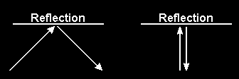
The radar beam
The beam of energy transmitted from the radar antenna is like
a torch beam. The radar signal continues outward from the
antenna until it is reflected (shined back), refracted (bent, like a
pencil placed in a glass of water) or absorbed.
The following diagrams demonstrate what happens to the
radar beam.
8
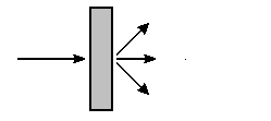

 Refraction
Absorption
Key information The radar beam continues outward until it is reflected,
refracted or absorbed.
Refraction
Absorption
Key information The radar beam continues outward until it is reflected,
refracted or absorbed.
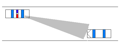
Radar beam angle
The width of the radar beam increases with distance. The beam
is cone shaped with a 12 spread. This is known as the main
signal beam. The further the beam extends from the
transmitter the wider it becomes.
Key information The main signal beam becomes wider the further from the
transmitter it becomes.
Beam range
The radar beam could continue outward from the antenna for
an indefinite distance. However, in reality the beam range is
the distance that the radar signal can be reflected back from a
target to the receiver. The range differs depending on the site.
Under ideal conditions the device should be able to detect
targets at a distance of one kilometre.
Key information The range of the radar beam differs depending on the site.
9
Factors affecting range
Atmospheric conditions such as rain, mist and fog will affect
the radar range and the return signal. Local terrain such as hills,
corners, fences and buildings will also have some effect.
NZ Police operated radar units have a sensitivity control that
can be adjusted to control the level of received return signal.
By adjusting the sensitivity operators can ensure the radar
signals received are optimal for the current environment.
Key information Radar range can be affected by atmosphere and terrain.
Operators can adjust the sensitivity of the radar to account for
problematic areas and weather.
Target reflectivity
The size and shape of the target vehicle’s surface will affect the
information sent back to the radar unit for processing into
speed readings. The bigger the target the better it will reflect
the signal back to the radar unit.
A target vehicle that is small and aerodynamically designed is a
poor reflector of a radar signal. This means it will need to be
closer to the unit to be picked up clearly.
Similarly, when a small vehicle is followed immediately by a
large vehicle the radar may return the speed of the larger
vehicle due to a stronger reflection. Operators must ensure
their tracking history covers such situations (see tracking
history later in this manual).
Key information The size and shape of the target vehicle affects the strength of
the reflected signal.
Doppler effect
The speed radar detects a movement between the transmitted
and received signal. This change in frequency is known as the
Doppler effect.
Simply, the radar unit determines the frequency difference
between the signal transmitted from the radar unit and the
signal reflected back from the moving target vehicle.
Key information The change in frequency between the signal transmitted and
the signal reflected back is the Doppler effect.
Tuning forks
Vibrating objects produce sound waves. A tuning fork illustrates
how a vibrating object can produce sound. The fork consists of
a handle and two tines. When the tuning fork is hit, the tines
begin to vibrate causing disturbances in the surrounding air
molecules and producing a ringing sound.
This is why tuning forks are used as part of the calibration and
daily testing of the radar unit. A particular speed reading is
confirmed when the sound (frequency) the fork produces is the
same as the Doppler frequency required. Each fork is stamped
with an operating band (frequency) and the speed the fork will
produce at that frequency.
It is important to note that because the movement of air
10
molecules from the fork goes from left to right you should
always present the side of the tine to the antenna.
Tuning forks should not be hit against hard objects as the tines
will bend out of shape and lose their ability to vibrate. The new
flat type of fork can be flicked by a finger or lightly struck
against another fork to produce the required signal level to
conduct daily testing.
Key information Tuning forks are used to simulate speed. Each fork is stamped
with an operating band (frequency) and the speed the fork
will produce at that frequency. They are used to check the
accuracy of the speed reading.
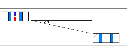
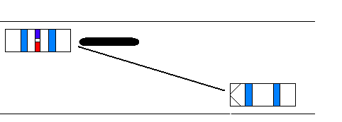
Cosine effect
In both stationary and moving modes a cosine effect occurs
when vehicles pass at an angle through the beam rather than
directly in line with it. The cosine effect is dependent on the
angle between the operator and the target vehicle.
The outcome of this effect is that measured speed will always
be less than true speed. This occurs because the measured
speed will be equal to the true speed less than the cosine of
the angle between the beam and direction of travel of the
target vehicle.
The larger the angle the lower the displayed speed on the
speed detection device. At 90 there will be no speed reading
as there is no relative motion between the axis of the antenna
and the target. At 0 the displayed speed will be the true speed
of the target vehicle. Due to the cosine effect target vehicles
travelling in a lane opposite the radar unit will always present a
lower reading than is true, as the target will be at an angle to
the main beam pointing down the road. The following table
and diagram demonstrate the effect of the cosine
angle.
Target true speed 100 kmh
Angle between radar Speed displayed
antenna and target
on radar receiver
0
100
10
98
20
93
30
86
40
76
As the table shows, for every degree the radar is off‐set to the
target vehicle the speed reading registers less than the true
speed of the target vehicle. The difference will always be in
favour of the target vehicle.
11
Key information Aiming the radar beam so that the cosine effect is minimised
gives a more accurate reading. Any speed difference between
true speed and the recorded speed will always be in the
favour of the target vehicle.
Radar – Stationary mode
Site selection is extremely important when operating radar in a
stationary mode. An operator must consider both operation
and safety considerations when selecting a location.
An ideal site is straight for at least 250 metres, with the road
surface slightly rising away from the radar unit and free from
undulations. Undulations will cause fading of the return signal.
Key information When selecting a site operation and safety must be
considered.
The radar beam is like a torch light beam. When setting up, the
operator should aim the antenna slightly towards the right‐
hand side of the road. The operator must listen to the Doppler
tone to ensure any targets are free from the fading that results
from a poorly aimed antenna or poor site selection. The aiming
of the beam is important to minimise the cosine effect and to
obtain a greater return signal.
Key information Correct aiming of the antenna minimises the cosine effect.
Site safety
When setting up a stationary site the operator should do so
without interfering with other traffic movements. The site
should allow the operator room to stop the offender using
hand signals without the need for pursuit. Safe and legal
parking should be available for the vehicles stopped.
The operator must make sure they and the target vehicle and
driver are safe when stopping them.
Hi visibility jackets maximise the operator’s visibility to road
users and enhance safety. They must be worn at all times when
the operator is out of the vehicle.
Key information The operator is responsible for their safety and the safety of
other road users.
Radar – Moving mode
The basics of stationary radar apply to radar used in moving
mode. However, there are some additional factors that must be
considered.
As stationary radar, the antenna receives only one signal.
However, in moving mode there are two received signals both
with different Doppler return frequencies.
12
 Ground speed
For the radar to operate in moving mode it must be able to
detect the ground speed of the patrol vehicle. There are times
when the traffic radar is unable to process ground speed and
when this happens the unit will show no speed readings.
Ground speed will be lost if:
the vehicle being detected is travelling at the same speed
as the patrol vehicle
there is heavy rain
the patrol vehicle is following a large vehicle, in which case
the ground speed beam may not obtain a reflection off the
road
the sensitivity is turned down too low.
Key information
Ground speed must be obtained before any target vehicle
enters the beam.
Opposite lane mode
The operating principles of “opposite lane mode” are simple. A
single radar frequency is transmitted from the moving patrol
vehicle. A portion of this signal is reflected off the ground about
15 metres directly in front of patrol vehicle and returned to the
antenna. This is called “ground speed” and is displayed in the
patrol speed window. As the ground speed is being measured
directly in front of the patrol vehicle, there is negligible cosine
effect and the displayed ground speed aligns with the true
speedometer indicated speed.
Example: A patrol vehicle travelling at 90 km/h and a target
vehicle travelling at 130 km/h produce a combined speed of
220 km/h. However, within the radar’s electronic processor
circuits, the radar unit subtracts the patrol ground speed from
the combined speed. This results in a target speed of 130 km/h.
It is vital that ground speed is obtained before any target
vehicle enters the beam. Without a ground speed reading the
unit cannot produce a target vehicle reading. Operators must
constantly monitor the patrol vehicle’s calibrated speedometer
to ensure the radar unit is displaying the correct ground speed.
Ground speed may be lost during heavy rain as the rain
droplets may absorb the radar signal. In this case operation of
the device should cease until the rain eases or stops.
Same‐lane mode
Same‐lane mode is used for vehicles travelling ahead of and in
the same direction as the patrol vehicle. The unit calculates the
difference between the ground speed of the patrol vehicle and
the target vehicle and this is depicted on the speed readout.
13
Deployment
Tracking history
Obtaining a proper tracking history of the target will effectively
eliminate errors. Tracking history is the ‘chain of evidence’ that
provides the operator with the assurance the target vehicle
speed is correctly captured by the radar equipment. Tracking
history for all radar contains three main elements:
visual observation
audio confirmation
radar verification.
Visual observation
There are three parts to visual observation, the operator must:
1 identify the target vehicle and continue to monitor its travel
2 confirm the target vehicle is within the radar’s range
3 estimate the target vehicle’s speed.
Audio confirmation
There are three parts to audio confirmation, the operator must:
1 listen for a clear Doppler tone
2 check the tone is consistent with the speed
3 check the level of the audio tone is strong and not
fluctuating or warbling.
Radar verification
There are four parts to radar verification:
1 the initial reading is consistent with the operator’s visual
observation and operator‐estimated speed
2 a steady target reading
3 readings consistent with visual observation and audio tone
4 ground speed readings confirmed by patrol speedometer.
When the operator is satisfied the target vehicle is producing
the correct reading they should lock the reading and take the
appropriate enforcement action. It is not always possible to
lock the target vehicle’s speed. Failure to lock the speed will
not prevent normal enforcement action being taken.
Possible sources of
In the super high frequencies of the spectrum where traffic
interference
radar operates (24‐38 GHz) the environment is relatively free of
noise and other non‐natural sources of interference. However,
interference may be experienced and it is important to know
how this occurs and what to do to eliminate it.
Many articles have been written about the types of
interference that will cause traffic radar to produce erroneous
readings, including:
street lighting systems
radar detectors
high voltage power lines
motor vehicle radiator fans
power transformers
neon signs
aircraft radar
microwave ovens.
14
NZ Police and the Measurement Standards Laboratory of New
Zealand (MSLNZ) conducted tests to determine if the potential
interference sources listed above had any effect on the traffic
radar equipment used by the NZ Police. No affects were found.
A point to consider is that aeroplanes contain more sensitive
radar equipment than traffic radar units. If the items listed
above generated significant interference radar would be too
dangerous for planes to use.
Even though some conditions may cause occasional
intermittent readings, most interference sources do not
produce any Doppler tone. If a clear Doppler tone is obtained
this will help to eliminate possible sources of interference. By
listening to the audible signal the officer can determine:
when the target entered the beam
if the estimated speed of the target is consistent with
Doppler tone
Note the higher the tone, the faster the target vehicle.
Radio transmitters
Radio energy detected near the traffic radar unit will blank off
any target readings, displaying “
rfi”. This tells the operator that
radio energy is present. The radio energy from a patrol car
radiotelephone or cross‐link will prevent readings when the
radiotelephone is transmitting.
Radio jammers
Over the years many people have tried to defeat radar speed
equipment. Most of these radio jamming devices do not work
and are nothing more than gimmicks. Units that do work
require large amounts of radar energy to be transmitted and
are prohibited in New Zealand by the Radio Communications
regulations.
Radar detectors
Radar detectors have a receiver that picks up the radar unit’s
transmitted energy and alerts the driver.
Operating the radar in hold mode means the transmitter is
turned off until required by the operator. The motorist with a
radar detector cannot be alerted to the radar when it is
operating in hold mode.
The operator can take the unit out of hold mode to obtain a
speed check and produce a valid speed‐reading before the
driver has time to react.
15
4.
Self‐paced test – Radar
1.
What are the three units that comprise traffic radar?
2.
There are three things that can happen to a radar wave, what are they?
3.
How can you minimise the cosine effect when using radar?
4.
Who is permitted to use radar speed enforcement equipment?
5.
What is the antenna component of traffic radar used for?
6.
Does the width of the beam remain the same the further from the transmitter it is
emitted?
7.
What factors can affect the radar range?
8.
What affect does vehicle size and shape have on the strength of the reflected signal?
9.
There are two major things that you need to consider when selecting a stationary
operating site, what are they?
10.
Establishing tracking history for all radar speed checks requires three elements, what
are they?
11.
Within each of the three elements required to establish tracking history there are a
number of parts. Detail what these are for each tracking history element.
12.
What are the tuning forks used for?
13.
What is the Doppler shift?
14.
Why is a certified speedometer required when operating traffic radar?
15.
What reasons are there for loss of ground speed?
16.
Is it a requirement to lock every speed reading when conducting an enforcement
stop?
16
5.
Laser speed detection
Introduction
Laser is an acronym for
Light
Amplification by
Stimulated
Emission of
Radiation. A laser is a concentration of light energy
into a narrow beam.
Principles of laser energy
To better understand how laser energy operates it helps to
understand the principles of light. Light is defined in
wavelengths similar to radio waves. The shorter the
wavelength, the higher the frequency. Visible light falls into a
fairly narrow section of the electromagnetic wave spectrum
with infra‐red light at one end with the longest wavelength,
and ultraviolet light at the other end with the shortest
wavelength.
As with radio waves, light waves can be reflected, refracted or
absorbed. Reflection of light is commonly seen in day‐to‐day
life. Refraction is when light is bent. Absorption is when light is
incorporated into the surroundings.
Key information A laser is a concentration of light energy into a high intensity
narrow beam.
Lasers
To build a laser we begin with a light source. This is placed in a
small cavity with two mirrors facing each other with the light
source in between. As the light reflects from one mirror to the
other, it passes through the light source and concentrates its
energy.
Laser light is found only in technology, never in nature. The
beam used is very narrow, much narrower than other light
sources such as a torch. It is also monochromatic (a single
wavelength and colour) and its narrow beam expands only
slightly over distance.
Traffic laser
While the traffic laser and traffic radar have much in common
there are also many differences. Similarities and differences are
highlighted throughout this section of the manual.
The traffic laser is an adaptation of laser to measure vehicle
speed. From the traffic laser unit laser light is directed through
focusing lenses toward the intended target.
The spread of a traffic laser beam is much less than that of
radar. The laser speed detection devices used by NZ police have
an approximate spread of 0.17. At a 100 metre range the laser
beam is only 0.3 metres wide. This allows the operator to aim
the traffic laser at specific vehicles allowing individual speed
measurement of vehicles in line of traffic.
NZ police laser devices use infrared laser light, so the beam is
invisible to the human eye.
17
Components
Unlike the traffic radar, the traffic laser is one unit. This laser
unit transmits the laser beam and receives it. The internal
computer calculates the target vehicle’s speed from the
changing distance readings received.
How it works
The operator aims the traffic laser at the target vehicle using
the unit aiming device. The laser beam is emitted in pulses.
When each laser pulse makes contact with the target vehicle
the laser beam is reflected back to the laser unit. The internal
computer calculates the time between each pulse and the
change in distance between the unit and target vehicle. This
enables the computer to accurately calculate the change in
each pulse (time/distance) and provide a readout of the target
vehicle’s speed.
The traffic laser can be used to check the speed of vehicles
approaching the laser and vehicles that are moving away from
the laser. Where vehicles are moving away from the unit this is
indicated by a – sign in the display.
Beam range
In theory the laser beam will continue outward for an indefinite
distance. However, in reality the beam range is the distance
that the laser beam can be reflected back from the target to
the laser unit, normally about 800 metres.
Measurement of distance
Traffic laser devices can be used to measure distance. The
accuracy of this type of device is limited to +/‐ 1 metre over all
distances displayed. It may be used in this way at crash scenes
and for engineering purposes.
Key information The laser beam extends outwards for an indefinite distance
unless it is reflected or refracted.
Site selection
There are a number of things that need to be taken into
account when selecting a laser operating site, including:
the cosine angle
having a clear line of sight
weather conditions
whether the operation is from inside the patrol vehicle
movement of the unit.
Key information When selecting an operating site the operator needs to
consider:
the cosine effect
having a clear line of sight
weather conditions
whether the operation is from inside the patrol vehicle
movement of the unit.
Cosine effect
The cosine effect applies equally to laser as it does to radar. To
minimise cosine effect follow the same guidelines as described
in the radar section.
Key information Correct sighting of the laser minimises the cosine effect.
18
Clear line of sight
As the laser uses light to measure speed, the beam must be
clear from device to target. Laser light will not bend or travel
through objects. The operator
must have a clear line of sight to
the target vehicle. That means the operator must see the
target vehicle clearly throughout the speed check. If their line
of site is blocked or temporarily interfered with the computer
will disregard all data and no speed reading will be displayed. If
the operator can see the object, the laser can see the object; if
the operator cannot see the object, the laser will not see it
either.
Key information There must be a clear line of sight to the target vehicle.
Weather conditions
Weather conditions are an important consideration in the
operation of the traffic laser. Fog, snow and heavy rain have
the potential to interfere with the laser’s operation. Therefore,
traffic laser is not to be used in fog, snow or heavy rain.
Key information Traffic laser is not to be used in fog, snow or heavy rain.
Operation from inside vehicles
The windscreen and side windows of the patrol vehicle can
affect the maximum range of the traffic laser. While the system
is designed to operate through windows, window tinting,
infrared and ultraviolet protections can reduce the effective
range of traffic laser. However, while range is affected, the
accuracy of the speed reading is not.
The best way to use the traffic laser is outside the vehicle or
through an open vehicle window.
Movement of vehicle
Operator movement will affect the traffic laser. Where the
device is not held firm, keeping motion to a minimum, the unit
will not display a speed reading. The reading will return when
the device is stabilised.
Other factors
A
sweep effect occurs when an operator changes aiming points
while conducting a vehicle speed check. When this happens,
the unit will not display a reading. To prevent this operators
must aim at a single point on the target vehicle for the entire
check (the registration plate is ideal).
Reflection influences occur on very hot days by heat rising and
causing reflection off the road, or from water lying on the road.
To avoid this influence, the operator should aim at the vehicle
and pay attention to any changes in the speed reading. A good
tracking history will verify the speed readings are correct.
Night operation and headlights will reduce the range of the
traffic laser. The headlights of newer model cars emit high
levels of infrared light, so may interfere with the laser’s ability
to detect the reflected laser pulse. To avoid this problem the
operator should aim between the headlights at the number
plate area on the target vehicle.
19
Target vehicle
Similar to using the traffic radar, the range of the laser beam
will depend on the target vehicle’s size and shape.
A large flat truck acts as a very good reflector of signals.
Sports cars with an aerodynamic design act as poor reflectors.
20
6.
Traffic laser
Introduction
The traffic laser can be operated only as a stationary device.
It may be used from inside or outside the patrol vehicle.
Key information The traffic laser can be used only as a stationary device.
Operating procedures
To maximise the deterrent effect of speed detection through
laser and ensure the safety of the public, the occupants of the
target vehicle and police, the following guidelines have been
developed.
Where traffic volumes are heavy, only vehicles travelling on the
same side as the parked patrol vehicle are to be targeted.
Motorcycle use
Laser speed detection equipment may be operated from
motorcycles subject to the requirements outlined in the Speed
Enforcement chapter of Police Instructions.
Tracking history
Like the radar, the traffic laser is only a tool used by the officer.
To establish that the speed check is accurate the operator must
establish a tracking history for the target vehicle. Tracking
history is obtained by three elements:
visual estimation of speed
audio tone confirmation
comparison of the digital readout with the operator
estimate of speed.
Key information Tracking history must be established using:
visual estimation of speed
audio tone confirmation
comparison of the digital readout with the operator
estimate of speed.
Sources of interference
Unlike radar devices, interference sources such as radios and
power lines do not have any effect on laser speed devices.
Anything the operator can see, the laser can see. If the
operator cannot see, the laser cannot see, for example, if
smoke is blowing across the road and blocking the operator’s
view, the laser will be prevented from detecting a target
through the smoke.
Locking on speed
Operators should lock on the speed reading and maintain it on
the device until the offender has had the opportunity to view
the reading. The only exception to this is when another officer
is operating the device and is remote from the officer stopping
the offender. In this case a note should be made of the
registered number of the vehicle, vehicle speed and/or
distance and time by the device operator.
Recording speed readings
The speed and distance at which the vehicle was checked
should be recorded on all offence notices, for example
130km/h at 400 metres.
21
Targeting vehicles
Officers should target vehicles travelling on the same side of
the road as the parked police vehicle in areas where traffic
volumes are heavy.
Remote operation
Officers may operate the device from any location (such as an
over‐bridge or side road), provided a second patrol in radio
contact is stationed on the road and is responsible for stopping
the offender. The operator must ensure that any locked speeds
are retained for viewing by an alleged offender, and that details
of speed, distance and vehicle description are recorded by the
device operator.
Targeting traffic travelling both On roads with low traffic volumes and speeds restricted to no
ways
more than 70 km/h, officers may target vehicles travelling in
any direction provided the method employed to stop the
offender is safe for all parties.
22
7.
Self‐paced test – Laser
1.
What sort of beam does a laser use?
2.
When selecting a site for operating a traffic laser what factors should be taken into
consideration?
3.
The traffic laser should not be used in certain weather conditions. Name these
conditions.
4.
What happens to the range if the laser is used through the windscreen of a patrol
vehicle?
5.
What effect does using the laser through the windscreen of a patrol vehicle have on
the accuracy of the unit’s speed reading?
6.
Where on a target vehicle should the laser be aimed?
7.
What effect do power lines have on laser units?
8.
When operating a laser how can the cosine effect be minimised?
9.
What effect does operator movement have on the target vehicle’s speed reading?
10.
When operating laser devices at night, what additional factors should operators
consider?
11.
Describe the effect that vehicle size and shape have when a traffic laser is operated.
12.
Which mode may the traffic laser be operated in? Stationary mode, moving mode or
both?
13.
What elements are required to establish tracking history?
23
8.
Operating principals
All speed enforcement devices used by the NZ Police are
Accuracy
required to have regular accuracy checks.
Certificate of accuracy
Section 146 of the Land Transport Act 1998 requires all
operational speed detectors’ certificates of accuracy be issued
within 12 months of the date the device is to be used in the
detection of offences. Only devices with current certificates of
accuracy may be operated.
A series of electronic and road tests form the basis of the
certificate of accuracy. The responsibility for testing and
certification rests with Police Calibration Services, an
International Standards Accredited Laboratory, based in
Wellington.
All speed enforcement devices are calibrated annually on a
district‐by‐district basis or when a device has been serviced.
Whenever a device is serviced it must be re‐calibrated before
being placed back in service.
Key information A certificate of accuracy is required for all speed enforcement
devices. This must be issued within 12 months of the date the
device is to be used.
The device must be checked to see if currently certified before
it is deployed.
Speedometer certificate
All police vehicles being used in conjunction with radar speed
detection equipment must have a current speedometer
certificate of accuracy. Section 146 of the Land Transport Act
1998 requires all speedometer certificates of accuracy to be
issued within 12 months of the date the device is used in the
detection of offences.
Operators using radar devices must check that the vehicle they
are using has a current speedometer certificate of accuracy.
This check is to be carried out before deployment (deployment
is the commencement of each shift).
Key information A speedometer certificate of accuracy is required for all
vehicles used to operate radar units. This must be issued
within 12 months of the day the vehicle is being used in
conjunction with radar equipment.
The speedometer certificate of accuracy must be checked
before the unit is deployed.
Testing
At the beginning of each shift operators must conduct the
series of tests prescribed in the operational guidelines to
ensure the device is operating correctly. This means at the
beginning of
every shift.
24
Pre‐deployment tests include internal circuitry tests and other
tests specified in the best practice guidelines for each device.
The operator must record the test results in the device
logbook. If the speed detection unit fails any checks it is not to
be used.
Key information The operator must complete the pre‐deployment tests before
using the device. Results of the tests must be recorded in the
logbook. If the unit fails any checks it must not be used.
Logbooks
Operators must complete the following information in the unit
logbook:
member’s name and QID
date and time of operations
test results
location
total hours of use
signature of operator
Serial numbers of all components
The operator must fill in a separate log sheet for each day of
operation.
Faulty units
If the device fails any tests it should not be used. The unit must
be returned to the New Zealand service agent who has been
appointed by the manufacturer.
When an instrument used in the testing of a speed
enforcement device (for example, a tuning fork) malfunctions
then both the unit and all testing equipment should be
packaged together and sent to the New Zealand service agent.
Details of the authorised service agents can be obtained from
Police Calibration Services.
After servicing by the agent, the unit will be re‐calibrated by
Police Calibration Services before being returned to the district.
All costs associated with repair (other than for normal wear
and tear) will be charged to the district.
25
9.
Evidential requirements
Documentary evidence
To comply with evidential requirements the operator will need:
a copy of the speed detection device logbook relating to
the day in question
a copy of the certificate of accuracy issued within a year of
the date of the offence
a copy of the certificate of accuracy for the patrol vehicle
used in the operation of the radar device or
a copy of the certificate of accuracy for the patrol vehicle
used for the weekly check in the case of a laser device
A copy of the operators Certificate of Proficiency for radar
and laser devices.
Evidence in court
The operator must be able to give in evidence that:
they are a certified speed detection equipment operator
they conducted the required tests for the unit and found it
to be working correctly
a tracking history was established for the target vehicle
the code of operations was complied with.
26
10. Operating guidelines ‐ Radar
Pre‐deployment tests
These are tests that are carried out before commencing speed
enforcement patrol.
Check the device is certified. A sticker is attached to the
unit that needs to be visually checked to confirm the date
for next calibration is in the future.
Check the speedometer of the patrol vehicle has a current
certificate of accuracy.
Switch on the device. Ensure all segments of the display are
operating. As the unit is turned on it will automatically run
through a series of internal tests. If these tests fail or if any
segment of the unit readout is not operating check to see
the power source and connections are in place. Turn the
device on again. If these tests fail again remove the unit
from service and forward it to the service agent.
Complete the tuning fork tests. The details of how these
tests are completed are contained in each device’s NZ
Police Operators Manual. Record the results in the
logbook. Tuning fork tests must be completed for each
antenna.
Note: all antennas must be checked.
Deployment tests
These are the tests that are completed while the unit is being
used in moving mode:
Confirm patrol vehicle speed is consistent with the speed
readout on the unit within +/‐ 3 km/h. This is achieved by
travelling at a consistent speed, appropriate to the speed
limit being operated in, and checking that the true speed
(according to the certificate of accuracy) is the one
displayed on the readout. Record the results in the
logbook.
27
11. Operating guidelines ‐ Laser
Pre‐deployment tests
These are tests that are carried out before commencing speed
enforcement patrol.
Check the device is certified. A sticker is attached to the
unit that needs to be visually checked to confirm the date
for next calibration is in the future.
Turn the unit on and check all display segments are
operating. The device will conduct a number of self‐tests,
commencing automatically. If the device is not operating or
if readout displays are not functioning check the power
supply and retest the unit. If these tests fail again remove
the unit from service and forward it to the service agent.
Up to here
Conduct the sight alignment test. This is carried out every
day the device is used. Select a pole or similar fixed point
marker and aim the unit sighter to the centre of the fixed
object; record the distance
. Move the aim of the laser to
the left‐hand side of the fixed point and check that the unit
ceases the reading on the fixed point as soon as the aim is
moved. Repeat this test but instead of moving the aim left,
move to the right‐hand side of the fixed point. Repeat
twice more, moving the aim above and below the fixed
point. The measurement displayed on the readout unit
must be recorded in the logbook.
Note. Determine a fixed point and target for use for all pre‐
deployment checks. The distance between these two points
must first be manually measured for use as a constant
reference.
Weekly testing
On a weekly basis the laser unit readout needs to be
checked using a drive though by a patrol vehicle with a
certified speedometer. This is carried out by having the
driver of the vehicle drive at a steady speed towards the
laser operation area. The speed will be relevant to the area
of operation. The driver should flash their headlights or
advise using the radio when the vehicle speed is steady and
the laser operator will check the speed. The member using
the laser will advise the vehicle driver of the results of the
speed check. The driver will advise the speed they were
travelling at after checking the certificate of accuracy to
determine the true speed. Where the margin of error
exceeds +/‐ 3 km/h the unit is to be withdrawn for
servicing. The results of the check must be recorded in the
logbook (vehicle speed/checked speed), for example
64/65; 46/46; 75/75.
28
12. Practical test requirements ‐ Radar
Training
The code of operations requires members to receive 20 hours
(16 hours radar, 4 hours laser) practical training in the
operation of speed enforcement equipment.
The following checklist describes the required competencies
that must be demonstrated to achieve certification.
Pre‐deployment tests
Device certification
The operator must:
Check the certification sticker on the side of the device for
the expiry date.
Explain that if the date is current the device can be used;
otherwise the device must be recertified before use.
Identify who carries out recertification.
Check the certificate of accuracy for the speedometer of
the patrol vehicle and determine its status — the test date
must be within 12 months from the date of operation.
Identify the difference, if any, between true vehicle speed
and actual vehicle speed readings.
Explain that for speed enforcement the true speed as
described in the certificate of accuracy is the speed used
for testing the device.
Unit testing
The operator must:
Assemble the radar device and install it in the vehicle.
Connect cables and power supply correctly.
Turn the device on and allow it to run its internal testing
sequence.
Check all readings are displayed completely, that means
there are no missing portions of letters or numbers.
Explain how to recheck and retest the device if the power
supply or readout does not work, by:
rechecking cables
checking connections
confirming the power source connection
turning the device off and restarting it
repeating the internal test sequence.
Tuning fork tests
The operator must:
Remove the tuning fork from storage.
Confirm the serial numbers on the tuning fork are the same
as listed on the certificate of accuracy for the radar device.
Record the tuning fork’s serial numbers in the logbook.
Conduct the tuning fork test sequence as detailed in the
unit operator’s manual (for both antennas if fitted).
Record the results of the tuning fork tests in the logbook.
29
Deployment tests
Moving mode
The operator must:
Confirm the patrol vehicle speed is consistent with the
speed readout on the device within +/‐3 km/h. This is
achieved by travelling at a consistent speed, appropriate to
the speed limit of the area and checking that the true
speed (according to the certificate of accuracy) is the one
displayed on the readout.
Record the results in the logbook.
Target identification
The operator must identify the target vehicle when it comes
into the beam.
Tracking history
The operator must demonstrate that they are able to establish
the tracking history of a vehicle. This means they:
See the target vehicle and specify what it looks like, for
example, a red Toyota or blue Mazda.
View the readout on the unit and identify to which vehicle
it relates.
Hear the change in audio (Doppler tone) to indicate an
increase or decrease in speed.
Cosine effect
The operator must:
Identify the target vehicle (using tracking requirements).
Use the antenna to demonstrate how a change in cosine
angle affects the speed reading.
Site
The site must:
Be straight enough to allow vehicles to be detected for at
least 100 metres (250 metres is preferred).
Provide sufficient distance to allow the speed to be
checked and the operator to exit the vehicle and conduct
an enforcement stop.
Unit set up
Aim
The operator must check the unit antenna:
is aimed and set up to:
detect vehicles
minimise the cosine angle and
Moving mode
The operator must:
Identify ground speed on the readout.
Confirm the ground speed and speedometer readout are
consistent (given the certificate of accuracy).
Place the unit in hold mode using the hold button.
Release the lock button for device operation.
Identify the target vehicle and its speed.
Establish a tracking history for the target vehicle using the
three elements ‐ visual, audio and readout.
Lock the target vehicle speed on the unit.
Indicate the difference between multiple and single
vehicles in the beam.
30
Patrol stops – moving mode
Same lane
The operator must:
Identify a target vehicle where its speed exceeds the
posted speed limit.
Establish a tracking history by telling the instructor how it
meets audio, visual and readout requirements.
Lock on the target vehicle’s speed.
Activate red and blue lights.
Pull out into the flow of traffic safely.
Indicate to the target vehicle to stop.
Park safely.
Ensure the reflectorised jacket is worn.
Exit the patrol vehicle after checking for traffic.
Approach the target vehicle’s driver’s door.
Keep following traffic in line of sight when speaking with
the driver.
Patrol stops – moving mode
Opposite lane
The operator must:
Identify a target vehicle where its speed exceeds the
posted speed limit.
Establish tracking history by telling the instructor how it
meets audio, visual and readout requirements.
Lock on the target vehicle’s speed.
Activate red and blue lights.
Complete a U‐turn safely and with due consideration to
minimise stress on the patrol vehicle (for example, speed is
reduced before turning; the kerb is not mounted when
turning).
Indicate to target vehicle to stop.
Park safely.
Ensure reflectorised jacket is being worn.
Exit patrol vehicle after checking for traffic.
Approach target vehicle’s driver’s door.
Keep following traffic in line of sight when speaking with
driver.
Issuing notice
The operator must:
Record the driver’s details on the notice.
Identify the appropriate offence.
Check the infringement fee is correct for the charge.
Record the appropriate precedent code.
Record the device serial numbers accurately on the notice.
Record a summary of the offence on the reverse of the
notice, including tracking history.
Complete all relevant sections of the preformatted officers’
notes field.
31
13. Practical test requirements ‐ Laser
Training
The following checklist describes the required competencies
that must be demonstrated to achieve certification.
Pre‐deployment tests
Device certification
The operator must:
Check the certification sticker on the side of the device for
the expiry date.
Explain if the date is current the device can be used,
otherwise the device must be recertified before use.
Identify who carries out recertification.
Unit testing
The operator must:
Connect the unit to the power supply correctly.
Turn the device on and allow it to run its internal testing
sequence.
Check all readings are displayed completely (no missing
portions of letters or numbers.)
Explain how to recheck and retest the device if the power
supply or readout does not work by:
confirming the power source connection
turning the device off and restarting it
proceeding with the internal test sequence.
Pre‐deployment
Pre‐deployment refers to the beginning of each shift.
Sight alignment test
The operator must:
Select a pole or fixed post object.
Aim the device at the object (using the heads up targeting
display) to obtain a distance reading (the distance between
the device and the fixed point as previously measured) and
advise the instructor of that distance.
Move the laser aim to either side of the fixed point and
check the distance reading ceases on movement from the
aimed point.
Move the laser aim from the fixed point above the point,
and check the distance reading ceases on movement from
the aimed point.
Move the laser aim from the fixed point below the point,
and check the distance reading ceases on movement from
the aimed point.
Record the test results in the unit logbook.
32
Weekly testing
The operator must provide instructions to the driver of a patrol
vehicle to conduct the weekly drive‐through test. The operator
must:
Establish that the vehicle has a current speedometer
certificate of accuracy.
Instruct the driver to drive towards the unit at a constant
speed.
Instruct the driver to flash their headlights or advise using
the radio when the check their vehicle speed.
Lock on the speed of the target patrol vehicle.
View the readout and ask the driver of the target patrol
vehicle for their true speed.
Confirm the target patrol vehicle speed and the readout on
the unit is within +/‐ 3 km/h.
Record the test results in the logbook.
Target identification
The operator must identify which vehicle is being detected
when a vehicle comes into the beam.
Tracking history
The operator must establish a tracking history of a vehicle. This
means:
Seeing the target vehicle and specifying what it looks like,
for example a red Toyota.
Viewing the readout on the unit and identifying to which
vehicle it relates.
Hearing the change in audio that indicates an increase or
decrease in speed.
Site selection
The operator must select a site for operation of the laser in
stationary mode. Selection must include the following
considerations.
Parking
The operator must consider:
Legal parking for the patrol vehicle.
Location safety for the patrol vehicle, including the officer’s
ability to open the patrol car door safely, exit the patrol
car, approach the offending vehicle, and conduct an
enforcement stop.
The range of laser operation is not within 250 metres of
any change in speed limit.
Legal parking in which to stop vehicles.
Safe parking for offending vehicles, including the ability for
the driver to safely exit their vehicle, and a safe approach
for the officer.
Day‐time and night‐time operation issues.
Site
The operating site must be straight for approximately 250
metres.
33
Unit set up
Aim
The operator must check the unit is:
aimed and set up to
detect vehicles
minimise the cosine effect
Issuing notice
The operator must:
Record the driver’s details on the notice.
Identify the appropriate offence.
Check the infringement fee is correct for the charge.
Record the appropriate precedent code.
Record the device serial number accurately on the notice.
Record the summary of the offence on the reverse of the
notice, including tracking history.
Complete all relevant sections of the preformatted officers’
notes field.
34
14. Answers for self‐paced test – Radar
1.
What are the three units that comprise traffic radar?
Transmitter, receiver and antenna.
2.
There are three things that can happen to a radar wave, what are they?
A radar wave can be reflected, refracted or absorbed.
3.
How can you minimise the cosine effect when using radar?
Aiming the radar beam so that the angle between the radar and the target vehicle
will minimise the cosine effect. Any speed difference between true speed and the
recorded speed will always be in the favour of the target vehicle.
4.
Who is permitted to use radar speed enforcement equipment?
Only police members who have been certified as trained operators are permitted to
use radar speed enforcement equipment.
5.
What is the antenna component of traffic radar used for?
The antenna is used to aim the microwave beam at the area being monitored.
6.
Does the width of the beam remain the same the further from the transmitter it is
emitted?
No, the further the beam extends from the radar the wider it becomes.
7.
What factors can affect the radar range?
Weather conditions such as rain, mist and fog will affect the radar range. Local
terrain such as hills, corners, fences and buildings will also have some effect. Road
undulations will also reduce the range and cause fading to the return signal.
8.
What affect does vehicle size and shape have on the strength of the reflected
signal?
The size and shape of the target vehicle’s surface will affect the information sent back
to the radar unit. The bigger the target the better it will act to reflect the signal back
to the radar unit. A target vehicle that is small and aerodynamically designed is a
poor reflector, which means it will need to be closer to the unit to be picked up
clearly.
9.
There are two major things that you need to consider when selecting a stationary
operating site, what are they?
Operation and safety are the two major considerations when selecting a site for
stationary mode operation.
10.
Establishing tracking history for all radar speed checks requires three elements,
what are they?
visual observation
audio confirmation
radar verification.
35
11.
Within each of the three elements required to establish tracking history there are a
number of parts. Detail what these are for each tracking history element.
visual observation
1. identify the target vehicle and continue to monitor its travel
2. confirm the target is within the radar’s range
3. estimate the target’s speed
audio confirmation
1. listen for a clear Doppler tone
2. check the Doppler tone is consistent with the speed.
3. check the level of the signal heard is strong and not fluctuating in audio
content
radar verification
1. check the initial reading is consistent with visual observation and the
operator estimated speed
2. ensure a steady target reading
3. check the readings are consistent with both visual observation and audio
tone
4. confirm ground speed readings by patrol speedometer
12.
What are the tuning forks used for?
Tuning forks are used to simulate speed. Each fork is stamped with an operating band
and speed and the fork will produce this when struck. It is then used to test that the
unit is detecting the speed accurately.
13.
What is the Doppler shift?
The speed radar detects a movement between the transmitted and received signal.
This change in frequency is known as the Doppler shift. Simply, the radar unit
determines the frequency difference between the signals transmitted from the radar
unit and the signals reflected from the moving target vehicle. The change in the tone
in the speaker is the Doppler shift frequency.
14.
Why is a certified speedometer required when operating traffic radar?
As part of the accuracy testing of the unit the speed of the patrol vehicle is checked
against the patrol speed detected by the radar unit. Before using the unit the match
between the patrol speed and the speed detected by the unit must be within +/‐ 3
km/h. This is used to confirm unit accuracy.
15.
What reasons are there for loss of ground speed?
Ground speed may be lost because of rain, a wet road surface, a badly sighted
antenna, or when the hold button is released without a clear road in front (the device
becomes confused and no reading is shown).
16.
Is it a requirement to lock every speed reading when conducting an enforcement
stop?
While it is preferred that the target vehicle speed is locked on before an enforcement
stop, this is not essential.
36
15. Answers for self‐paced test – Laser
1.
What sort of beam does a laser use?
A laser is a concentration of light energy into a high intensity beam.
2.
When selecting a site for operating a traffic laser what factors should be taken into
consideration?
The operator must consider:
the cosine angle
a clear line of sight
weather conditions
whether the operation is from inside the patrol vehicle
movement of unit
other factors, such as sweep effect, reflection influences and night
operation.
3.
The traffic laser should not be used in certain weather conditions. Name these
conditions.
The traffic laser should not be operated in fog, snow and heavy rain.
4.
What happens to the range if the laser is used through the windscreen of a patrol
vehicle?
Range is reduced if used through the windscreen of a patrol vehicle.
5.
What effect does using the laser through the windscreen of a patrol vehicle have
on the accuracy of the unit’s speed reading?
Although range is reduced there is no effect on the accuracy of speed readings.
6.
Where on a target vehicle should the laser be aimed?
The operator should aim the laser between the headlights at the number plate of the
target vehicle.
7.
What effect do power lines have on laser units?
Power lines have no effect on laser units.
8.
When operating a laser how can the cosine effect be minimised?
The position of the traffic laser to the roadway creates an angle that reduces the
speed reading of the target vehicle. While the angle cannot be eliminated entirely (to
do so the operator would need to be in the middle of the road), it can be minimised
by the operator reducing the angle to a minimum.
9.
What effect does operator movement have on the target vehicle’s speed reading?
Operator movement cause the laser unit speed reading to disappear. The speed
reading will return when the device is stabilised.
10.
When operating laser devices at night‐time, what additional factors should
operators consider?
Night operation and headlights will reduce the range of the traffic laser. Headlights of
newer cars may also interfere with the laser’s ability to detect the reflected laser
pulse. To avoid this, the operator should aim between the vehicle’s headlights at the
number plate area.
37
11.
Describe the effect that vehicle size and shape have when a traffic laser is
operated.
The larger the vehicle the easier it is to detect. Small, aerodynamically designed
vehicles are harder to detect and will be closer to the laser before a reading is
obtained.
12.
Which mode may the traffic laser be operated in? Stationary mode, moving mode
or both?
Laser is operated in stationary mode only.
13.
What elements are required to establish tracking history?
Tracking history is established using:
visual estimation of speed
audio tone
comparison of the digital readout with the operator estimate of speed.
38
CODE OF OPERATIONS – SPEED DETECTION EQUIPMENT
This Code of Operations governs the operation of all speed detection equipment used by the
New Zealand Police. It has been jointly prepared and agreed to by the Measurement Standards
Laboratory of New Zealand (MSLNZ) and the New Zealand Police.
Operators
1
Trained Operators
Except for the purposes of instruction, speed detection equipment is to be operated only
by members of the NZ Police who have:
completed the speed detection operators manual
achieved a minimum of 80% in the manual theory test
undergone 20 hours, practical instruction with a qualified instructor and
demonstrated competence
been certified as a trained operator by the National Manager: Road Policing.
Former members of the Ministry of Transport Traffic Safety Service who completed
training in the use of speed detection equipment prior to 1992 are deemed to be
qualified operators. This covers members whose identification numbers begin E002 up
to and including F116.
2
Qualified Instructors
District Road Policing Managers have the authority to appoint qualified instructors. To
be appointed as a qualified instructor, staff must have been certified as a trained
operator and:
Have spent at least two years consistently operating speed detection equipment
are currently using speed detection equipment as part of their regular duties
have the ability to train others
Qualified instructors
must be registered with the Road Policing Support (Police National
Headquarters) before taking up a qualified instructor role.
Equipment 3
Certificate of Accuracy
Section 146 of the Land Transport Act 1998 requires all operational speed detection
equipment certificates of accuracy to be issued within 12 months of the date used in the
detection of offences. Only units with current certificates of accuracy may be operated.
A series of electronic and road tests form the basis of the issue of the certificate of
accuracy. The responsibility for testing and certification rests with Police Calibration
Services, an International Standards Accredited Laboratory, based in Wellington.
4
Speedometer Certificate
All police vehicles being used in conjunction with radar speed detection and the field
testing of laser speed detection equipment must have a current speedometer certificate
of accuracy. Section 146 of the Land Transport Act 1998 requires all speedometer
Version 2013/01
certificates of accuracy to be issued within 12 months of the date used in the detection
of offences.
5
Servicing
Repairs and servicing are only to be carried out by authorised service agents. Details of
authorised service agents are maintained by Police Calibration Services.
Pre‐deployment 6
Testing
At the beginning of each deployment operators must conduct the series of tests
prescribed in the Speed Detection Equipment Operators Manual to ensure that the
device is operating correctly. The operator must record test results in the device
logbook. If the speed detection unit fails any checks it is not to be used.
Deployment 7
Tracking History
A tracking history of a vehicle must be established. Tracking history for all speed
detection units contains three main elements:
visual observation
audio confirmation
verification by a speed detector.
To eliminate errors effectively, all three elements must be present for each speed check.
For radar units operated in moving mode, the vehicle ground speed must be confirmed
by certified speedometer.
8
Multiple Vehicles in Beam
Where there is more than one vehicle in the beam, enforcement action may be taken,
providing the operator can give evidence relating to the tracking history of other vehicles
and the offender’s speed.
9
Fairness
Operators must use their training and experience to ensure that there are no significant
sources of reflection or interference in the vicinity of the offence. If there is ever any
doubt concerning the speed check or the operation of the speed detection unit, no
action is to be taken.
…………………………………………….
………………………………………………
Dr Tim Armstrong
Superintendent Carey Griffiths
Manager Time and Frequency Standards
National Manager: Road Policing
Measurement Standards NZ Ltd
NZ Police
Date : 1 March 2013
Date: 1 March 2013
40