
DETAIL DESIGN ROAD SAFETY AUDIT
SH1 WAIKATO EXPRESSWAY 110 KM/H SPEED
REVIEW PROJECT HAMPTON DOWNS
1982
PREPARED FOR WAKA KOTAHI NZ TRANSPORT AGENCY
29 September 2021
Act
Information
Official
the
under
Released
This document has been prepared for the benefit of Waka Kotahi NZ Transport Agency. No liability is
accepted by this company or any employee or sub-consultant of this company with respect to its use by
any other person.
This disclaimer shall apply notwithstanding that the report may be made available to other persons for an
application for permission or approval to fulfil a legal requirement.
QUALITY STATEMENT
1982
PROJECT MANAGER
ROAD SAFETY AUDIT TEAM LEADER
s 9(2)(a)
s 9(2)(a)
Act
PREPARED BY
s 9(2)(a)
s 9(2)(a)
29 September 2021
CHECKED BY
s 9(2)(a)
29 September 2021
REVIEWED BY
s 9(2)(a)
Information
29 September 2021
APPROVED FOR ISSUE BY
s 9(2)(a)
29 September 2021
Official
the
AUCKLAND
Level 3 Stantec House, 111 Carlton Gore Road, Newmarket, Auckland 1023
PO Box 13-052, Armagh, Christchurch 8141
under
TEL +64 9 580 4500
Released
Stantec │ SH1 Waikato Expressway 110 km/h Speed Review Project Hampton Downs │ 29 September 2021
Status: Final │ Project No.: 310201124 Child No.: 100.0101705 │ Our ref: WEX 110 Hampton Downs Detail RSA Designer, RSE, Client
Response
Abbreviations
ATP
audio tactile profiled (road marking)
RRPM
reflectorised raised pavement marker
SH1 State
Highway
1
1982
Waka Kotahi
Waka Kotahi NZ Transport Agency
Act
Information
Official
the
under
Released
Stantec │ SH1 Waikato Expressway 110 km/h Speed Review Project Hampton Downs │ 29 September 2021
Status: Final │ Project No.: 310201124 Child No.: 100.0101705 │ Our ref: WEX 110 Hampton Downs Detail RSA Designer, RSE, Client Response │
Page i
Waka Kotahi NZ Transport Agency
SH1 Waikato Expressway 110 km/h Speed Review Project Hampton Downs
CONTENTS
1982
Abbreviations ...................................................................................................................................................... i
1
Introduction ............................................................................................................................................ 1
1.1
Safety Audit Definition and Purpose ...................................................................................................... 1
Act
1.2
The Project .............................................................................................................................................. 2
1.3
The Road Safety Audit Team ................................................................................................................. 2
1.4
Previous Road Safety Audits .................................................................................................................. 2
1.5
Scope of this Road Safety Audit ............................................................................................................ 2
1.6
Briefing, Site Visit, Audit, Exit Meeting .................................................................................................... 2
1.7
Report Format ......................................................................................................................................... 2
1.8
Documents Provided ............................................................................................................................. 3
1.9
Disclaimer ............................................................................................................................................... 4
Information
2
Safety Concerns .................................................................................................................................... 5
2.1
Cross-section .......................................................................................................................................... 5
2.2
Maintenance Bays ................................................................................................................................. 6
2.3
Barriers ..................................................................................................................................................... 8
2.4
Road Signs and Markings ..................................................................................................................... 10
Official
3
Audit Statement ................................................................................................................................... 14
4
Response and Decision Statements .................................................................................................... 15
the
4.1
Designer’s Responses ........................................................................................................................... 15
4.2
Safety Engineer’s Comments (if applicable) ...................................................................................... 15
4.3
Project Manager’s Decisions ............................................................................................................... 15
4.4
Designer’s Statement ........................................................................................................................... 15
4.5
Safety Audit Close Out ......................................................................................................................... 16
under
5
References ........................................................................................................................................... 17
LIST OF TABLES
Table 1-1: Crash Frequency Descriptor .............................................................................................................. 3
Table 1-2: Concern Assessment Rating Matrix ................................................................................................... 3
Table 1-3: Concern Categories .......................................................................................................................... 3
Released
Table 1-4: Drawing titles ...................................................................................................................................... 4
Stantec │ SH1 Waikato Expressway 110 km/h Speed Review Project Hampton Downs │ 29 September 2021
Status: Final │ Project No.: 310201124 Child No.: 100.0101705 │ Our ref: WEX 110 Hampton Downs Detail RSA Designer, RSE, Client Response
LIST OF FIGURES
Figure 1: Proposed edge details ......................................................................................................................... 5
Figure 2: Maintenance access bay Type 2 ........................................................................................................ 7
Figure 3: Hampton Downs northbound exit ramp gore and nose (Google, 2021) ........................................ 11
Figure 4: Existing buffer strip Rangiriri to Ohinewai (Google, 2021) ................................................................. 12
Figure 5: Exit ramp cyclist crossing at Cambridge (west) interchange (Google, 2019) ................................. 12 1982
Act
Information
Official
the
under
Released
Stantec │ SH1 Waikato Expressway 110 km/h Speed Review Project Hampton Downs │ 29 September 2021
Status: Final │ Project No.: 310201124 Child No.: 100.0101705 │ Our ref: WEX 110 Hampton Downs Detail RSA Designer, RSE, Client Response
1
Introduction
1.1
Safety Audit Definition and Purpose
A road safety audit is a term used internationally to describe an independent review of a future road
project to identify any safety concerns that may affect the safety performance. The audit team considers
the safety of all road users and qualitatively reports on road safety issues or opportunities for safety
improvement.
1982
A road safety audit is therefore a formal examination of a road project, or any type of project which
affects road users (including cyclists, pedestrians, mobility impaired etc.), carried out by an independent
competent team who identify and document road safety concerns.
Act
A road safety audit is intended to help deliver a safe road system and is not a review of compliance with
standards.
The primary objective of a road safety audit is to deliver a project that achieves an outcome consistent
with Safer Journeys and the Safe System approach, which is a safe road system free of death and serious
injury. The road safety audit is a safety review used to identify all areas of a project that are inconsistent
with a Safe System and bring those concerns to the attention of the client so that the client can make a
value judgement as to appropriate action(s) based on the risk guidance provided by the safety audit
team.
The key objective of a road safety audit is summarised as:
‘to deliver completed projects that contribute towards a safe road system that is free of death and serious
injury by identifying and ranking potential safety concerns for all road users and others affected by a road
Information
project.’
A road safety audit should desirably be undertaken at project milestones such as:
concept stage (part of business case);
scheme or preliminary design stage (part of pre-implementation);
detail design stage (pre-implementation or implementation); or
Official
pre-opening or post-construction stage (implementation or post-implementation).
A road safety audit is not intended to be a technical or financial audit and does not substitute for a design
check of standards or guidelines. Any recommended treatment of an identified safety concern is intended
the
to be indicative only, and to focus the designer on the type of improvements that might be appropriate. It
is not intended to be prescriptive and other ways of improving the road safety or operational problems
identified should also be considered.
In accordance with the procedures set down in the NZTA Road Safety Audit Procedures for Projects
Guidelines - Interim release May 2013 the audit report should be submitted to the client who will instruct the
designer to respond. The designer should consider the report and comment to the client on each of any
under
concerns identified, including their cost implications where appropriate, and make a recommendation to
either accept or reject the audit report recommendation.
For each audit team recommendation that is accepted, the client will make the final decision and brief
the designer to make the necessary changes and/or additions. As a result of this instruction the designer
shall action the approved amendments. The client may involve a safety engineer to provide commentary
to aid with the decision.
Decision tracking is an important part of the road safety audit process. A decision tracking table is
embedded into the report format at the end of each set of recommendations. It is to be completed by
the designer, safety engineer, and client for each issue, and should record the designer’s response, client’s
decision (and asset manager's comments in the case where the client and asset manager are not one
Released
and the same) and action taken.
A copy of the report including the designer's response to the client and the client's decision on each
recommendation shall be given to the road safety audit team leader as part of the important feedback
loop. The road safety audit team leader will disseminate this to team members.
29 September 2021 │ Status: Final │ Project No.: 310201124 Child No.: 100.0101705 │ Our ref: WEX 110 Hampton Downs Detail RSA Designer,
RSE, Client Response
Page 1
1.2
The Project
Roadside and median safety barriers are to be installed along sections of the SH1 Waikato Expressway
between Hampton Downs and Tamahere to provide continuous protection and to meet the safety criteria
for raising the speed limit from 100 km/h to 110 km/h.
1.3
The Road Safety Audit Team
This road safety audit has been carried out in accordance with the NZTA Road Safety Audit Procedure for
Projects Guidelines – Interim release May 2013, by:
1982
Keith Weale, Stantec,
Tegwen Atkinson, Stantec, and
Act
Heather Liew, Waka Kotahi.
1.4
Previous Road Safety Audits
There have been no previous road safety audits of the current project.
1.5
Scope of this Road Safety Audit
This is a detail design road safety audit of the proposed installation of roadside and infill median barriers
along the Hampton Downs section of the Waikato Expressway between the Meremere section (opened in
2006 and retrofitted with side and median barriers in 2017) and the Longswamp Section (opened in 2019).
The 1.6 km Hampton Downs section is located between RP486/7.28 and RP 486/8.80 and includes the
entrance and exit ramps of the Hampton Downs diamond interchange.
Information
Although preliminary status is shown on the drawing set referred to in Section 1.8 of this report, BBO
confirmed that the drawings were intended for a detail design road safety audit.
1.6
Briefing, Site Visit, Audit, Exit Meeting
Mclean Hastie and Jeremy Froger of BBO, Shane Small of Waka Kotahi, and Thayalan Sivachelvan of Blue
Barn (seconded to Waka Kotahi) briefed the road safety audit team on Friday 17 September 2021, after
Official
which the road safety audit team undertook a desktop audit via MS Teams.
A site visit was not permitted due to Auckland being under Covid-19 Level 4 restrictions on movement and
two of the road safety audit team members being based in Auckland. The safety audit team therefore
conducted the safety audit using Google Street View images and Argonaut Roadrunner videos.
the
An exit meeting was held with the designers and Waka Kotahi representatives later that afternoon.
1.7
Report Format
The potential road safety problems identified have been ranked as follows.
under
The expected crash frequency is qualitatively assessed on the basis of expected exposure (how many
road users will be exposed to a safety issue) and the likelihood of a crash resulting from the presence of the
issue. The severity of a crash outcome is qualitatively assessed on the basis of factors such as expected
speeds, type of collision, and type of vehicle involved.
Reference to historic crash rates or other research for similar elements of projects, or projects as a whole,
have been drawn on where appropriate to assist in understanding the likely crash types, frequency and
likely severity that may result from a particular concern.
The frequency and severity ratings are used together to develop a combined qualitative risk ranking for
each safety issue using the concern assessment rating matrix in Table 1-2. The qualitative assessment
requires professional judgement and a wide range of experience in projects of al sizes and locations.
Released
In ranking specific concerns, the auditors have considered the objectives of the Safe System approach, i.e.
to minimise fatal or serious injury crashes.
In undertaking this assessment, the safety audit team has utilised the following descriptor tables to enable
a fair and reasonable rating of the risks.
29 September 2021 │ Status: Final │ Project No.: 310201124 Child No.: 100.0101705 │ Our ref: WEX 110 Hampton Downs Detail RSA Designer,
RSE, Client Response
Page 2
Table 1-1: Crash Frequency Descriptor
Crash Frequency
Indicative Description
Frequent Multiple
crashes
(more than 1 per year)
Common
1 every 1-5 years
Occasional
1 every 5-10 years
Infrequent
Less than 1 every 10 years
1982
Crash severity is determined on the likelihood of a crash resulting in death or serious injury. The reader is
advised that the severity of an injury is determined in part by the ability of a person to tolerate the crash
forces. An able-bodied adult will have a greater ability to recover from higher trauma injuries, whereas an
elderly person may have poor ability to recover from high trauma injuries. The auditors consider the likely
Act
user composition, and hence the likely severity of injury to that user.
Table 1-2: Concern Assessment Rating Matrix
Severity
Frequency (probability of a crash)
(likelihood of death or
serious injury)
Frequent
Common
Occasional
Infrequent
Very likely
Serious
Serious
Significant
Moderate
Likely
Serious
Significant
Moderate
Moderate
Unlikely
Significant
Moderate
Minor
Minor
Information
Very unlikely
Moderate
Minor
Minor
Minor
While all safety concerns should be considered for action, the client or nominated project manager will
make the decision as to what course of action will be adopted based on the guidance given in this
ranking process with consideration to factors other than safety alone. As a guide a suggested action for
each concern category is given in Table 1-3. Official
Table 1-3: Concern Categories
Concern
Suggested action
Major safety concern that must be addressed and requires changes to avoid
the
Serious
serious safety consequences.
Significant safety concern that should be addressed and requires changes to
Significant
avoid serious safety consequences.
Moderate
Moderate safety concern that should be addressed to improve safety.
Minor
Minor safety concern that should be addressed where practical to improve safety.
under
In addition to the ranked safety issues, it may be appropriate for the safety audit team to provide
additional comments with respect to items that may have a safety implication but lie outside the scope of
the safety audit. A comment may include items where the safety implications are not yet clear due to
insufficient detail for the stage of project, items outside the scope of the audit such as existing issues not
impacted by the project or an opportunity for improved safety but not necessarily linked to the project
itself. While typically comments do not require a specific recommendation, the auditors may give
suggestions in some instances.
1.8
Documents Provided
Released
The road safety audit team was provided with the following documents for this audit.
147130-02 WEX Hampton Downs - Barriers Set for RSA_v1.pdf as shown in Table 1-4.
Hampton Downs 110 Speed Review DPS_v1.pdf
29 September 2021 │ Status: Final │ Project No.: 310201124 Child No.: 100.0101705 │ Our ref: WEX 110 Hampton Downs Detail RSA Designer,
RSE, Client Response
Page 3
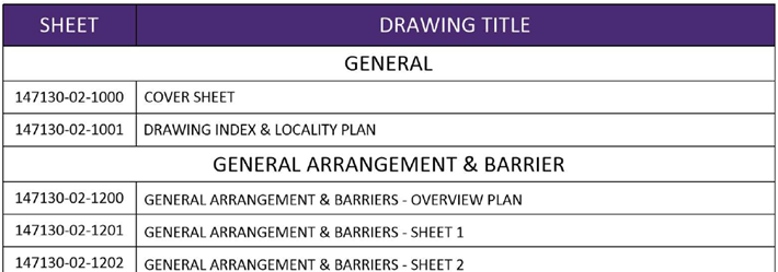
Detailed drawings titled ‘Key Corridor Safety Retrofit Programme Waikato Expressway (SH1) Hampton
Downs Section’ (dated 9 September 2021) were produced by BBO. These drawings and a design
philosophy statement were provided to the road safety audit team on Wednesday 15 September 2021.
New signage to reflect the proposed 110 km/h speed limit changes was not included in the scope of this
road safety audit.
Table 1-4: Drawing titles
1982
Act
Information
1.9
Disclaimer
The findings and recommendations in this report are based on an examination of available relevant plans,
the specified road and its environs, and the opinions of the road safety audit team. However, it must be
recognised that eliminating safety concerns cannot be guaranteed since no road can be regarded as
Official
absolutely safe and no warranty is implied that all safety issues have been identified in this report. Safety
audits do not constitute a design review nor are they an assessment of standards with respect to
engineering or planning documents.
the
Readers are urged to seek specific technical advice on matters raised and not rely solely on the report.
While every effort has been made to ensure the accuracy of the report, it is made available on the basis
that anyone relying on it does so at their own risk without any liability to the safety audit team or their
organisations.
under
Released
29 September 2021 │ Status: Final │ Project No.: 310201124 Child No.: 100.0101705 │ Our ref: WEX 110 Hampton Downs Detail RSA Designer,
RSE, Client Response
Page 4
2
Safety Concerns
A site visit was not permitted due to Auckland being under Covid-19 Level 4 restrictions on movement and
two of the road safety audit team members being based in Auckland. The safety audit team therefore
conducted the safety audit using Google Street View images and Argonaut Roadrunner videos.
2.1
Cross-section
2.1.1 Shoulder widths and lighting columns
1982
Moderate
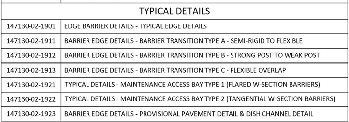
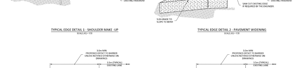
The design philosophy statement and the typical edge details on drawing 147130-02-1901 indicate that,
although the existing shoulder next to kerbs is about 2.5 m wide, the barrier will always be installed with a
3.0 m minimum offset from the edge line. Where there are no kerbs, the seal is proposed to be widened to
Act
3.0 m. The design philosophy statement states that, ‘…for 110 km/h retro fit projects is to retain existing
lighting where practicable. Where existing columns are in front of or clash with new barrier, they will be
relocated behind the new barrier clear of the deflection zone.’ The general arrangement drawings
tabulate exactly where each edge design applies. Thus, in all cases, there should be enough width for a
vehicle to stop and for the passenger door to be opened.
Information
Official
the
under
Figure 1: Proposed edge details
However, the lighting columns that would need to be relocated are not identified on the drawings, thus
placing the onus on the contractor to determine which ones are to be shifted. There is also no criterion
shown for how close the barrier can be to the lighting column before it needs to be shifted. Theoretically,
Released
the drawings could allow the back of the barrier to touch the lighting column.
The safety concern is that the desired 3.0 m width will not eventuate if it is left to the contractor to
determine which lighting columns are to be relocated, especially if the existing lighting column position is
only just shy of meeting the requirements and the barrier is shifted to miss the column or to achieve the
desired clearance to the lighting column. The two lighting columns, each about 40 m behind the nose of
29 September 2021 │ Status: Final │ Project No.: 310201124 Child No.: 100.0101705 │ Our ref: WEX 110 Hampton Downs Detail RSA Designer,
RSE, Client Response
Page 5
the two exit ramps, are examples where the flare of the barriers meeting the crash cushions needs to be
accounted for.
Recommendation(s)
1. Show the lighting columns on the typical edge details with the minimum acceptable gap between the
back of the barrier and the face of the lighting column dimensioned, and also on the general
arrangement drawings, so that there can be no ambiguity concerning which lighting columns are to
be relocated and which can remain in place.
1982
Frequency
Severity
Rating
Crashes are likely to be
Death or serious injury is
The safety concern is
infrequent
likely
moderate
Designer
Designer agrees.
Act
response
The drawings now detail where columns are to be relocated.
An additional edge detail has been added to the drawing set for
Barrier behind
existing kerb – with lighting column. The minimum gap between back barrier and
light column is 150mm. Survey indicates there is space to accommodate barrier and
150mm gap between kerb and column in most instance. Where this is not achieved
columns are shown to be relocated.
The general arrangement plans also note the requirement for lighting to be
relocated where the 150mm gap cannot be achieved.
Safety Engineer
Agree with SAT. Designer to add lighting columns to the drawing set.
comment
Information
Julian Chisnall, Team Lead Road Safety, Programme and Standards:
Current best practice is to provide 1.5m between the back of the barrier system and
the front face of the lighting column to mitigate the risk of an errant vehicle
deflecting the barrier and striking the column. In locations where the 1.5mtr offset
clearance cannot be achieved, 1mtr gap would be acceptable (but not desirable).
Client decision
Agree with SAT and RSE.
Scope to include the relocation of light columns beyond the barrier deflection zone
Official
(min 1mtr gap).
Action taken
The design has been updated, indicating the relocation of affected light columns
the
2.2
Maintenance Bays
2.2.1 Manoeuvring space
Moderate
under
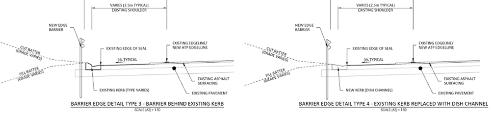
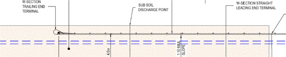
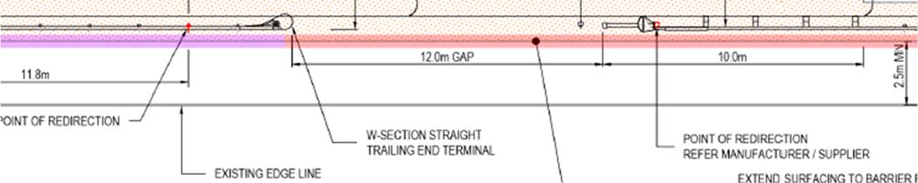
The proposed Type 2 maintenance bay, which is intended to give access to the berm in both directions, is
shown in Figure 2.
The designers explained entry would be in the forward direction, as opposed to reversing into the bay.
Released
29 September 2021 │ Status: Final │ Project No.: 310201124 Child No.: 100.0101705 │ Our ref: WEX 110 Hampton Downs Detail RSA Designer,
RSE, Client Response
Page 6
1982
Act
Figure 2: Maintenance access bay Type 2
The effective width of the maintenance bay would be less than the 4 m width shown when the widths of
the end terminals are taken into account. There is thus unlikely to be enough width for a maintenance
truck to manoeuvre into the maintenance bay from the shoulder and a portion of the through lane will
likely be required for the manoeuvre. Similarly, exiting the bay might require the front of the vehicle to
swing wide into the adjacent lane. This would mean blocking the through lane while manoeuvring in or
out, effectively bringing all traffic in that lane to an unexpected halt. This would be unsafe, not only for the
general traffic, but also for the maintenance personnel.
Information
The possibility of using a lane closure traffic management plan with attenuation vehicles was discussed.
However, the risk is that a maintenance person might try to use the bay not realising that it required a
special temporary traffic management plan.
Furthermore, the gap in the roadside barrier will leave any worker of vehicle in the maintenance bay
exposed to the risk of a vehicle leaving the road at that point.
Recommendation(s)
Official
1. Amend the design to a disengaging overlapping barrier layout that will al ow maintenance vehicle
drivers to pull over onto the shoulder first and then access the maintenance bay without encroaching
into the adjacent though lane, while also fully shielding the maintenance vehicle and any personnel in
the maintenance bay. This may require additional access bays or alternative arrangements to service
the
the berm.
Frequency
Severity
Rating
Crashes are likely to be
Death or serious injury is
The safety concern is
infrequent
likely
moderate
Designer
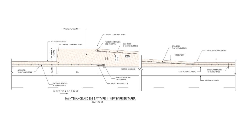
The Type 2 layout has been removed and replaced with a Type 1 layout. The Type 1 layout
under
response allows the vehicle to pull onto the shoulder and reverse into the maintenance bay where
they are isolated from the main carriageway by w-section barrier.
The shoulder is widened to 3.5m on approach and departure from the maintenance bay to
allow additional space to enter and exit. The 3.5m width includes a traversable dish channel
to replace kerb and channel where required.
Safety
Concur with SAT and Designer. Type 1 layout supplied by the designer addresses the
Engineer
concerns raised by SAT.
commen
t
Released
29 September 2021 │ Status: Final │ Project No.: 310201124 Child No.: 100.0101705 │ Our ref: WEX 110 Hampton Downs Detail RSA Designer,
RSE, Client Response
Page 7
1982
Act
Client
Agree with SAT, Designer and RSE.
decision
The type 1 layout has been included within the scope.
Action
No further action required
taken
Information
2.3
Barriers
2.3.1 Deflection to lighting columns
Minor
As discussed in Section 2.1.1, the existing and even the relocated lighting columns are likely to be within
Official
the expected operating width of the semi-rigid barriers. The performance of the barriers and of the slip
base lighting columns would be unpredictable in a crash.
It is acknowledged that the installation of the roadside barriers would be a significant safety improvement,
the
even if they were not installed in accordance with accepted normal operating clearances. However,
consideration may not have been given to mitigating the departure, like using a stiffer less deflective
barrier system such as one of the Thrie-beam barrier systems.
Recommendation(s)
1. Mitigate the consequence of the close gap between the lighting columns and the back of the
roadside barrier by using a stiffer less deflective barrier system.
under
2. In conjunction with the recommendation above, specify on the cross-section edge details what
minimum clearance between the lighting columns and the back of the barrier is sought. Refer also to
Section 2.1.1.
3. Where lighting columns are to be relocated, specify ground-planted frangible lighting columns to
replace the slip-base columns.
Frequency
Severity
Rating
Crashes are likely to be
Death or serious injury is
The safety concern is
occasional
unlikely
minor
Designer
1. Post spacing will be halved for 12m on approach and 6m on departure from
Released
response
lighting columns in the deflection width of the barrier system used.
This wil be added to the construction drawing set.
2. A minimum gap of 150mm is specified between existing lighting columns
and new barrier.
3. New columns behind barrier will be ground planted collapsible.
29 September 2021 │ Status: Final │ Project No.: 310201124 Child No.: 100.0101705 │ Our ref: WEX 110 Hampton Downs Detail RSA Designer,
RSE, Client Response
Page 8
Safety Engineer
Concur with SAT and Designer. Designer to provide 1mtr workable width between
comment
back of the barrier to front of a lighting column.
Julian Chisnall, Team Lead Road Safety, Programme and Standards:
The proposal to reduce the post spacings will do little to mitigate the risk with a
weak post W-beam system similar to that already installed. Halving the post spacing
(from 1905mm down to 952mm) will reduce likely dynamic deflection by 15%,
perhaps 20% at best.
Client decision
Agree with SAT and RSE.
1982
Scope to include the relocation of light columns beyond the barrier deflection zone
(min 1mtr gap).
Action taken
The design has been updated, indicating the relocation of affected light columns
Act
2.3.2 Median barrier
Moderate
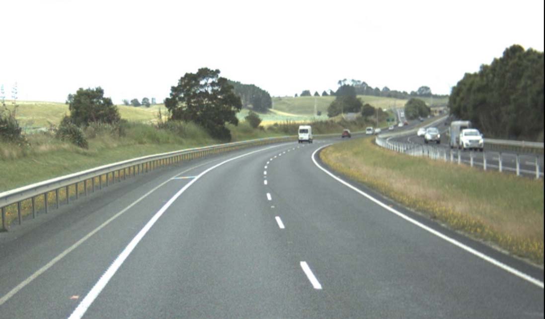
The drawings show an existing flexible barrier along the edge of the median shoulder of northbound
carriageway. There is no median barrier proposed for the southbound carriageway.
Although the existing northbound carriageway barrier would probably prevent a cross-median head-on
crash in the southbound direction, even given the higher probable impact angle, the median turf is likely
to be soft and wet in winter. High centre of gravity vehicles such as SUVs are susceptible to roll-over
crashes when hitting a soft berm even if it is deemed to be fully traversable in theory.
Information
Recommendation(s)
1. Consider installing median barriers wherever there is a likelihood of a rollover crash due to soft turf in
the median. This recommendation should apply to the full length of the Waikato Expressway under
consideration in this 110 km/h project.
Frequency
Severity
Rating
Official
Crashes are likely to be
Death or serious injury is
The safety concern is
common
unlikely
moderate
Designer
The Designer acknowledges this is a risk. However, except for the short section under
response
the interchange bridge, modification to the median is not part of the project scope.
the
Safety Engineer Agree with SAT.
comment
Client decision
Agree with Designer.
Following a discussion with Principal Traffic and Safety Engineer Richard Landon-Lane
on 08/12/2021, the southbound direction right-hand curve at the northern extent of
the proposed 110km threshold (RS/RP 486/7.28) predominantly means any run-off
under
road vehicles will likely vear to the left-hand-side, so the risk of a vehicle entering the
right-hand side median turf in minimal.
Also, the existing median barrier/turf layout is also present at other locations across
the state highway network and should be reviewed at a regional/national level.
Released
29 September 2021 │ Status: Final │ Project No.: 310201124 Child No.: 100.0101705 │ Our ref: WEX 110 Hampton Downs Detail RSA Designer,
RSE, Client Response
Page 9
1982
Act
Action taken
No further action required
2.4
Road Signs and Markings
Information
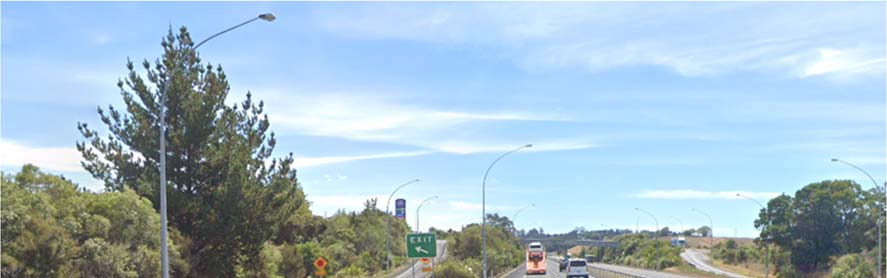
2.4.1 Gore signs and markings
Minor
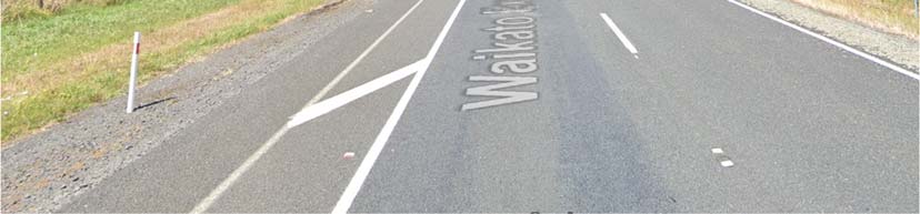
The existing exit and entrance ramp gore areas have no hatching. Since there will now be crash cushions
on the exit noses, thus reducing the area on and behind the noses for recovery, both exit ramps would
benefit from increased visibility. It is acknowledged that the interchange is lit, but speeds will be higher.
Official
All exit gores should be marked with diagonal chevron bars for consistency along the Waikato Expressway.
Te Kauwhata, Rangiriri and Huntly interchanges are marked, but Hampton Downs and Ohinewai
interchanges are not.
The drawings do not indicate how or if the exit signs on the noses are to be relocated to allow the crash
the
cushion to be installed.
under
Released
29 September 2021 │ Status: Final │ Project No.: 310201124 Child No.: 100.0101705 │ Our ref: WEX 110 Hampton Downs Detail RSA Designer,
RSE, Client Response
Page 10
1982
Act
Figure 3: Hampton Downs northbound exit ramp gore and nose (Google, 2021)
Information
Recommendation(s)
1. Mark the exit and entrance gore areas with diagonal chevron bars. Apply this to all exits on the
Waikato Expressway for consistency.
2. Indicate where the exit signs are to be relocated behind the installed crash cushions.
Frequency
Severity
Rating
Official
Crashes are likely to be
Death or serious injury is
The safety concern is
infrequent
unlikely
minor
Designer
1. Chevron markings have been added to the drawings for installation at the
response
exit’s. the
2. Exit signs will be relocated behind the crash cushion.
This will be added to the construction drawing set.
Safety Engineer
Concur with SAT and Designer.
comment
Client decision
Agree with SAT, Designer and RSE.
under
Action taken
No further action required
2.4.2 Cyclist signs and markings
Comment
The designers confirmed that cyclists would still be allowed to use the 110 km/h sections of the Waikato
Expressway.
Released
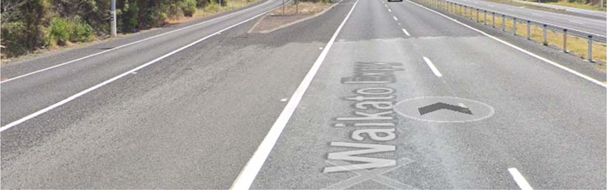
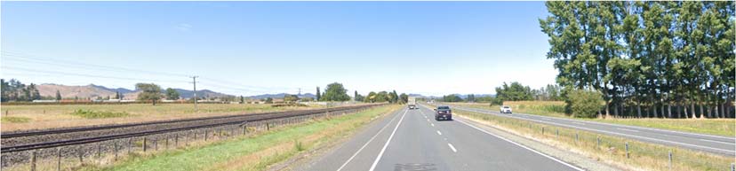
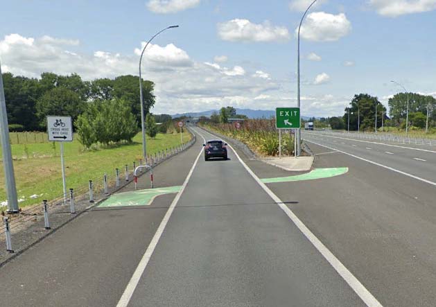
Some sections of the existing Waikato Expressway cater for cyclists in the form of painted buffer strips (e.g.
Rangiriri to Ohinewai shown in Figure 4 below) and signed crossing points across exit and entrance ramps.
shown in Figure 5 below. The latter is in an existing 110 km/h speed limit zone. Such shoulder buffers and
cyclist crossings are not present on the Hampton Downs section or other recently opened sections such as
the Huntly Bypass.
29 September 2021 │ Status: Final │ Project No.: 310201124 Child No.: 100.0101705 │ Our ref: WEX 110 Hampton Downs Detail RSA Designer,
RSE, Client Response
Page 11
1982
Act
Figure 4: Existing buffer strip Rangiriri to Ohinewai (Google, 2021)
Information
Official
the
under
Figure 5: Exit ramp cyclist crossing at Cambridge (west) interchange (Google, 2019)
Ag, it would be reasonable to assume that some drivers would not expect to encounter cyclists in such an
environment and would therefore not be looking out for cyclists.
While the buffer strips and signed crossing points provide no physical protection for cyclists, the signs and
markings may remind drivers to be on the lookout for cyclists. The converse
may also be true—where the
signs and markings end or are not present, drivers may think that cyclists are not al owed on the
expressway.
Released
A consistent philosophical approach should be taken regarding the provision of cyclist signs and markings
along the entire length of the Waikato Expressway.
Designer
The Designer agrees that a consistent approach would be beneficial. Cycle
response
markings can be added if required by Waka Kotahi. Similar to the Rangiriri exits.
Safety Engineer
Concur with SAT and Designer. Cycle markings to be added similar to the Rangiriri
comment
exits.
29 September 2021 │ Status: Final │ Project No.: 310201124 Child No.: 100.0101705 │ Our ref: WEX 110 Hampton Downs Detail RSA Designer,
RSE, Client Response
Page 12
Client decision
Agree with SAT, Designer and RSE.
Cycle markings to be included within scope.
Action taken
Cycle markings have been added to the drawings.
2.4.3 RRPMs and ATP
Comment
1982
The ATP markings applied on the recent Longswamp to Rangiriri project (June 2020) coincided with the
RRPMs. Not only did the application cover the RRPMs in many cases, but the raised portion of the ATP also
tended to mask the full effectiveness of the RRPM reflectivity, effectively reducing the RRPM to about half
Act
its reflective area when viewed from the low angle of a passenger vehicle.
For ease of application of the ATP markings (i.e. not having to stop the machine at each RRPM) and to
improve the reflectivity of the RRPMs, perhaps the RRPMS could be placed just to the left of the ATP
marking.
Designer
ATP will be refreshed as part of the project. South of the interchange the ATP is offset
response
beside the edge line with a gap at RRPM’s. North of the southern ramps ATP is on the
edge line with RRPM’s offset beside the edge line.
Any new ATP will be installed beside the edge line. ATP installation requirements will
be added to the construction drawing set.
Information
Safety Engineer
Agree with Designer.
comment
Client decision
Agree with SAT. Designer and RSE.
Action taken
The design has been updated, indicating the location of RRPMs and ATP
Official
the
under
Released
29 September 2021 │ Status: Final │ Project No.: 310201124 Child No.: 100.0101705 │ Our ref: WEX 110 Hampton Downs Detail RSA Designer,
RSE, Client Response
Page 13


3
Audit Statement
We declare that we remain independent of the design team and have not been influenced in any way by
any party during this road safety audit.
We certify that we have used the available plans, and have examined the specified roads and their
environment, to identify features of the project we have been asked to look at that could be changed,
removed, or modified in order to improve safety.
We have noted the safety concerns that have been evident in this audit and have made
recommendations that may be used to assist in improving safety.
1982
s 9(2)(a)
Signed
Date 21 September 2021
Act
s 9(2)(a)
Principal Transportation Engineer, Stantec
s 9(2)(a)
Signed
Date 21 September 2021
s 9(2)(a)
Project Transportation Engineer, Stantec
Information
Signed
Date 29 September 2021
Heather Liew, BEng(Hons), MET
Safety Engineer, Waka Kotahi
Official
the
under
Released
29 September 2021 │ Status: Final │ Project No.: 310201124 Child No.: 100.0101705 │ Our ref: WEX 110 Hampton Downs Detail RSA Designer,
RSE, Client Response
Page 14


4
Response and Decision Statements
System designers and the people who use the roads must all share responsibility for creating a road system
where crash forces do not result in death or serious injury.
4.1
Designer’s Responses
I have studied and considered the auditors’ safety concerns and recommendations for safety
improvements set out in this road safety audit report and I have responded accordingly to each safety
concern with the most appropriate and practical solutions and actions, which are to be considered further
1982
by the safety engineer (if applicable) and project manager.
s 9(2)(a)
Act
Signed
Date 08/12/2021
s 9(2)(a)
Design Manager, BBO]
4.2
Safety Engineer’s Comments (if applicable)
I have studied and considered the auditors’ safety concerns and recommendations for safety
improvements set out in this road safety audit report together with the designer’s responses. Where
appropriate, I have added comments to be taken into consideration by the project manager when
deciding on the action to be taken.
s 9(2)(a)
Information
Signed
Date 03 December, 2021
[Shashi Lakshminarasimhaiah, Safety Engineer, NZTA]
4.3
Project Manager’s Decisions
Official
I have studied and considered the auditors’ safety concerns and recommendations for safety
improvements set out in this road safety audit report, together with the designer’s responses and the
comments of the safety engineer (if applicable) and having been guided by the auditor’s ranking of
the
concerns have decided the most appropriate and practical action to be taken to address each of the
safety concerns.
Signed
Date 08/12/2021
under
[Shane Small, BE(Civil), Project Manager, NZTA]
4.4
Designer’s Statement
I certify that the project manager’s decisions and directions for action to be taken to improve safety for
each of the safety concerns have been carried out.
s 9(2)(a)
Signed
Date 08/12/2021
Released
s 9(2)(a)
29 September 2021 │ Status: Final │ Project No.: 310201124 Child No.: 100.0101705 │ Our ref: WEX 110 Hampton Downs Detail RSA Designer,
RSE, Client Response
Page 15
4.5
Safety Audit Close Out
The project manager is to distribute the audit report incorporating the decisions to the designer, safety
audit team leader, safety engineer, and project file.
Date:…08/12/2021…………………………….
1982
Act
Information
Official
the
under
Released
29 September 2021 │ Status: Final │ Project No.: 310201124 Child No.: 100.0101705 │ Our ref: WEX 110 Hampton Downs Detail RSA Designer,
RSE, Client Response
Page 16
5
References
Google. (2019, December). Street View.
Google. (2021, February). Street View.
1982
Act
Information
Official
the
under
Released
29 September 2021 │ Status: Final │ Project No.: 310201124 Child No.: 100.0101705 │ Our ref: WEX 110 Hampton Downs Detail RSA Designer,
RSE, Client Response
Page 17
 Auckland
Level 3 Stantec House, 111 Carlton Gore Road
Newmarket, Auckland 1023
PO Box 13-052, Armagh
Christchurch 8141
Tel +64 9 580 4500
1982
Please visit
www.stantec.com to learn more about how
Stantec design with community in mind.
Act
Information
Official
the
under
Released