
DETAIL DESIGN ROAD SAFETY AUDIT
SH1 WAIKATO EXPRESSWAY 110 KM/H SPEED
REVIEW PROJECT TAMAHERE
1982
PREPARED FOR WAKA KOTAHI NZ TRANSPORT AGENCY
26 October 2021
Act
Information
Official
the
under
Released
This document has been prepared for the benefit of Waka Kotahi NZ Transport Agency. No liability is
accepted by this company or any employee or sub-consultant of this company with respect to its use by
any other person.
This disclaimer shall apply notwithstanding that the report may be made available to other persons for an
application for permission or approval to fulfil a legal requirement.
QUALITY STATEMENT
1982
PROJECT MANAGER
ROAD SAFETY AUDIT TEAM LEADER
s 9(2)(a)
s 9(2)(a)
Act
PREPARED BY
s 9(2)(a)
s 9(2)(a)
26 October 2021
CHECKED BY
s 9(2)(a)
26 October 2021
REVIEWED BY
s 9(2)(a)
Information
26 October 2021
APPROVED FOR ISSUE BY
s 9(2)(a)
26 October 2021
Official
the
under
AUCKLAND
Level 3 Stantec House, 111 Carlton Gore Road, Newmarket, Auckland 1023
PO Box 13-052, Armagh, Christchurch 8141
TEL +64 9 580 4500
Released
Stantec │ SH1 Waikato Expressway 110 km/h Speed Review Project Tamahere │ 26 October 2021
Status: Final │ Project No.: 310201124 Child No.: 100.0101906 │ Our ref: WEX 110 Tamahere Detail RSA - Designer RSE Client Response (v2)
(002)
Abbreviations
ATP
audio tactile profiled (road marking)
RRPM
reflectorised raised pavement marker
SH1 State
Highway
1
1982
Waka Kotahi
Waka Kotahi NZ Transport Agency
Act
Information
Official
the
under
Released
Stantec │ SH1 Waikato Expressway 110 km/h Speed Review Project Tamahere │ 26 October 2021
Status: Final │ Project No.: 310201124 Child No.: 100.0101906 │ Our ref: WEX 110 Tamahere Detail RSA - Designer RSE Client Response (v2) (002)
│ Page i
Waka Kotahi NZ Transport Agency
SH1 Waikato Expressway 110 km/h Speed Review Project Tamahere
CONTENTS
1982
Abbreviations ...................................................................................................................................................... i
1
Introduction ............................................................................................................................................ 1
1.1
Safety Audit Definition and Purpose ...................................................................................................... 1
Act
1.2
The Project .............................................................................................................................................. 2
1.3
The Road Safety Audit Team ................................................................................................................. 2
1.4
Previous Road Safety Audits .................................................................................................................. 2
1.5
Scope of this Road Safety Audit ............................................................................................................ 2
1.6
Briefing, Site Visit, Audit, Exit Meeting .................................................................................................... 3
1.7
Report Format ......................................................................................................................................... 3
1.8
Documents Provided ............................................................................................................................. 4
1.9
Disclaimer ............................................................................................................................................... 4
Information
2
Safety Concerns .................................................................................................................................... 5
2.1
Barriers ..................................................................................................................................................... 5
2.2
Maintenance Bays ............................................................................................................................... 13
2.3
Road Signs and Markings ..................................................................................................................... 14
3
Audit Statement ................................................................................................................................... 17
Official
4
Response and Decision Statements .................................................................................................... 18
4.1
Designer’s Responses ........................................................................................................................... 18
the
4.2
Safety Engineer’s Comments (if applicable) ...................................................................................... 18
4.3
Project Manager’s Decisions ............................................................................................................... 18
4.4
Designer’s Statement ........................................................................................................................... 18
4.5
Safety Audit Close Out ......................................................................................................................... 18
5
References ........................................................................................................................................... 20
under
LIST OF TABLES
Table 1-1: Crash Frequency Descriptor .............................................................................................................. 3
Table 1-2: Concern Assessment Rating Matrix ................................................................................................... 3
Table 1-3: Concern Categories .......................................................................................................................... 4
Released
LIST OF FIGURES
Figure 1: Project location .................................................................................................................................... 2
Figure 2: Median barrier (Google, 2021) ............................................................................................................ 5
Stantec │ SH1 Waikato Expressway 110 km/h Speed Review Project Tamahere │ 26 October 2021
Status: Final │ Project No.: 310201124 Child No.: 100.0101906 │ Our ref: WEX 110 Tamahere Detail RSA - Designer RSE Client Response (v2) (002)
Figure 3: Bridge barrier (Google, 2021) .............................................................................................................. 5
Figure 4: Roadside barriers across gul y (Google, 2021) .................................................................................... 6
Figure 5: Flexible to semi-rigid barrier transition detail ....................................................................................... 7
Figure 6: Proposed barriers along northbound exit ramp .................................................................................. 7
Figure 7: Trees and lighting column along northbound exit ramp (Google, 2021) .......................................... 8
Figure 8: Proposed barriers along northbound entrance ramp ........................................................................ 8
Figure 9: Trees and lighting column along northbound entrance ramp (Google, 2021)................................. 9 1982
Figure 10: Proposed barriers along southbound exit ramp................................................................................ 9
Figure 11: Trees and lighting column along southbound exit ramp (Google, 2021) ...................................... 10
Act
Figure 12: Proposed barriers along southbound entrance ramp .................................................................... 11
Figure 13: Lighting column near southbound entrance ramp merge ............................................................ 11
Figure 14: Lighting column close to edge of expressway (Google, 2021) ...................................................... 12
Figure 15: Maintenance access bay detail ..................................................................................................... 13
Figure 16: Proposed location of maintenance bays ....................................................................................... 13
Figure 17: Exit ramp cyclist crossing at Cambridge (west) interchange (Google, 2019) ............................... 15
Figure 18: Existing RRPM position in relation to edge line ................................................................................ 16
Information
Official
the
under
Released
Stantec │ SH1 Waikato Expressway 110 km/h Speed Review Project Tamahere │ 26 October 2021
Status: Final │ Project No.: 310201124 Child No.: 100.0101906 │ Our ref: WEX 110 Tamahere Detail RSA - Designer RSE Client Response (v2) (002)
1
Introduction
1.1
Safety Audit Definition and Purpose
A road safety audit is a term used internationally to describe an independent review of a future road
project to identify any safety concerns that may affect the safety performance. The audit team considers
the safety of all road users and qualitatively reports on road safety issues or opportunities for safety
improvement.
1982
A road safety audit is therefore a formal examination of a road project, or any type of project which
affects road users (including cyclists, pedestrians, mobility impaired etc.), carried out by an independent
competent team who identify and document road safety concerns.
Act
A road safety audit is intended to help deliver a safe road system and is not a review of compliance with
standards.
The primary objective of a road safety audit is to deliver a project that achieves an outcome consistent
with Safer Journeys and the Safe System approach, which is a safe road system free of death and serious
injury. The road safety audit is a safety review used to identify all areas of a project that are inconsistent
with a Safe System and bring those concerns to the attention of the client so that the client can make a
value judgement as to appropriate action(s) based on the risk guidance provided by the safety audit
team.
The key objective of a road safety audit is summarised as:
‘to deliver completed projects that contribute towards a safe road system that is free of death and serious
injury by identifying and ranking potential safety concerns for all road users and others affected by a road
Information
project.’
A road safety audit should desirably be undertaken at project milestones such as:
concept stage (part of business case);
scheme or preliminary design stage (part of pre-implementation);
detail design stage (pre-implementation or implementation); or
Official
pre-opening or post-construction stage (implementation or post-implementation).
A road safety audit is not intended to be a technical or financial audit and does not substitute for a design
check of standards or guidelines. Any recommended treatment of an identified safety concern is intended
the
to be indicative only, and to focus the designer on the type of improvements that might be appropriate. It
is not intended to be prescriptive and other ways of improving the road safety or operational problems
identified should also be considered.
In accordance with the procedures set down in the NZTA Road Safety Audit Procedures for Projects
Guidelines - Interim release May 2013 the audit report should be submitted to the client who will instruct the
designer to respond. The designer should consider the report and comment to the client on each of any
under
concerns identified, including their cost implications where appropriate, and make a recommendation to
either accept or reject the audit report recommendation.
For each audit team recommendation that is accepted, the client will make the final decision and brief
the designer to make the necessary changes and/or additions. As a result of this instruction the designer
shall action the approved amendments. The client may involve a safety engineer to provide commentary
to aid with the decision.
Decision tracking is an important part of the road safety audit process. A decision tracking table is
embedded into the report format at the end of each set of recommendations. It is to be completed by
the designer, safety engineer, and client for each issue, and should record the designer’s response, client’s
decision (and asset manager's comments in the case where the client and asset manager are not one
Released
and the same) and action taken.
A copy of the report including the designer's response to the client and the client's decision on each
recommendation shall be given to the road safety audit team leader as part of the important feedback
loop. The road safety audit team leader will disseminate this to team members.
26 October 2021 │ Status: Final │ Project No.: 310201124 Child No.: 100.0101906 │ Our ref: WEX 110 Tamahere Detail RSA - Designer RSE
Client Response (v2) (002)
Page 1
 1.2
The Project
1.2
The Project
Roadside and median safety barriers are to be installed along sections of the SH1 Waikato Expressway
between Hampton Downs and Tamahere to provide continuous protection and to meet the safety criteria
for raising the speed limit from 100 km/h to 110 km/h.
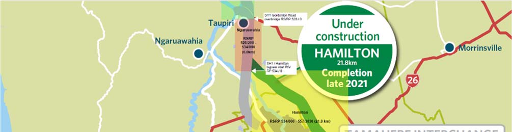
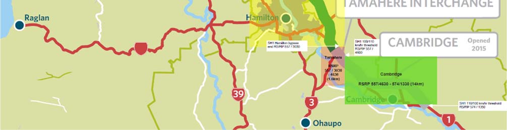
The Tamahere project location is shown circled in blue in Figure 1. It comprises the short 1.5 km section
between the southern end of the Hamilton Bypass (under construction) and the northern end of the
Cambridge Bypass, which was competed in 2015.
1982
Act
Information
Figure 1: Project location
Flexible roadside protection barriers are proposed on both sides of the expressway from the south-facing
Official
ramps of the Tamahere interchange to the existing roadside barriers installed along the Cambridge Bypass.
No alterations to the existing back-to-back semi-rigid median barrier are proposed. The roadside shoulders
are to be widened to provide 3 m between the face of the barrier and the edge line.
the
1.3
The Road Safety Audit Team
This road safety audit has been carried out in accordance with the NZTA Road Safety Audit Procedure for
Projects Guidelines – Interim release May 2013, by:
Keith Weale, Stantec,
under
Tegwen Atkinson, Stantec, and
Heather Liew, Waka Kotahi.
1.4
Previous Road Safety Audits
There have been no previous road safety audits of the current project.
1.5
Scope of this Road Safety Audit
This is a detail design road safety audit of the proposed installation of roadside barriers along the
Released
Tamahere section of the Waikato Expressway between the south-facing entrance and exit ramps of the
Tamahere diamond interchange and the existing flexible roadside barriers along the Cambridge Bypass
section.
The designers are contemplating extending the barriers along the ramps of the Tamahere interchange and
thus asked the road safety audit team to include the interchange ramps in the safety audit.
26 October 2021 │ Status: Final │ Project No.: 310201124 Child No.: 100.0101906 │ Our ref: WEX 110 Tamahere Detail RSA - Designer RSE
Client Response (v2) (002)
Page 2
1.6
Briefing, Site Visit, Audit, Exit Meeting
Lydia Gray of WSP (the designers) and Jeremy Froger of BBO, Shane Small of Waka Kotahi, and Thayalan
Sivachelvan of Blue Barn (seconded to Waka Kotahi) briefed the road safety audit team on Wednesday 13
October 2021, after which the road safety audit team undertook a desktop audit via MS Teams.
A site visit was not permitted due to Auckland and Waikato being under Covid-19 Level 3 restrictions on
movement and gatherings, and two of the road safety audit team members being based in Auckland. The
safety audit team therefore conducted the safety audit using Google Street View images and Argonaut
Roadrunner videos.
1982
An exit meeting was held with the designers and Waka Kotahi representatives later that afternoon.
1.7
Report Format
Act
The potential road safety problems identified have been ranked as follows.
The expected crash frequency is qualitatively assessed on the basis of expected exposure (how many
road users will be exposed to a safety issue) and the likelihood of a crash resulting from the presence of the
issue. The severity of a crash outcome is qualitatively assessed on the basis of factors such as expected
speeds, type of collision, and type of vehicle involved.
Reference to historic crash rates or other research for similar elements of projects, or projects as a whole,
have been drawn on where appropriate to assist in understanding the likely crash types, frequency and
likely severity that may result from a particular concern.
The frequency and severity ratings are used together to develop a combined qualitative risk ranking for
each safety issue using the concern assessment rating matrix in Table 1-2. The qualitative assessment
requires professional judgement and a wide range of experience in projects of al sizes and locations.
Information
In ranking specific concerns, the auditors have considered the objectives of the Safe System approach, i.e.
to minimise fatal or serious injury crashes.
In undertaking this assessment, the safety audit team has utilised the following descriptor tables to enable
a fair and reasonable rating of the risks.
Table 1-1: Crash Frequency Descriptor
Crash Frequency
Indicative Description
Official
Frequent Multiple
crashes
(more than 1 per year)
Common
1 every 1-5 years
Occasional
1 every 5-10 years
the
Infrequent
Less than 1 every 10 years
Crash severity is determined on the likelihood of a crash resulting in death or serious injury. The reader is
advised that the severity of an injury is determined in part by the ability of a person to tolerate the crash
forces. An able-bodied adult will have a greater ability to recover from higher trauma injuries, whereas an
elderly person may have poor ability to recover from high trauma injuries. The auditors consider the likely
under
user composition, and hence the likely severity of injury to that user.
Table 1-2: Concern Assessment Rating Matrix
Severity
Frequency (probability of a crash)
(likelihood of death or
serious injury)
Frequent
Common
Occasional
Infrequent
Very likely
Serious
Serious
Significant
Moderate
Likely
Serious
Significant
Moderate
Moderate
Released
Unlikely
Significant
Moderate
Minor
Minor
Very unlikely
Moderate
Minor
Minor
Minor
While all safety concerns should be considered for action, the client or nominated project manager will
make the decision as to what course of action will be adopted based on the guidance given in this
26 October 2021 │ Status: Final │ Project No.: 310201124 Child No.: 100.0101906 │ Our ref: WEX 110 Tamahere Detail RSA - Designer RSE
Client Response (v2) (002)
Page 3
ranking process with consideration to factors other than safety alone. As a guide a suggested action for
each concern category is given in Table 1-3.
Table 1-3: Concern Categories
Concern
Suggested action
Major safety concern that must be addressed and requires changes to avoid serious
Serious
safety consequences.
Significant safety concern that should be addressed and requires changes to avoid
Significant
serious safety consequences.
1982
Moderate
Moderate safety concern that should be addressed to improve safety.
Minor
Minor safety concern that should be addressed where practical to improve safety.
Act
In addition to the ranked safety issues, it may be appropriate for the safety audit team to provide
additional comments with respect to items that may have a safety implication but lie outside the scope of
the safety audit. A comment may include items where the safety implications are not yet clear due to
insufficient detail for the stage of project, items outside the scope of the audit such as existing issues not
impacted by the project or an opportunity for improved safety but not necessarily linked to the project
itself. While typically comments do not require a specific recommendation, the auditors may give
suggestions in some instances.
1.8
Documents Provided
The road safety audit team was provided with the following documents for this audit.
2-32875.31
C01 to C02
Rev A
General layout plan
Information
2-32875.31 C03
Rev
A
Typical
section
2-32875.31
C04
Rev A
Maintenance bay detail
2-32875.31
C05
Rev A
Barrier transition type 1
2-32875.31
C06
Rev A
Barrier transition type 2
SNP Tamahere Barriers Memo for RSA prepared by WSP (dated 7.10.2021)
Official
The fol owing supporting drawings of the Hamilton Bypass were provided for information only
3311244-DR-CG-0738
Rev 1
Plan and longitudinal section of southern tie-in
3311244-DR-CG-0739
Rev B
Plan and longitudinal section of southern tie-in
the
3311244-DR-CB-0738
Rev 3
Barriers at southern tie-in (issued for construction)
3311244-DR-CB-0739
Rev B
Barriers at southern tie-in (not for construction)*
In addition to the above, an email titled ‘SNP Tamahere barriers on ramps and gore areas’ (dated
12.10.2021) was provided. This email outlined high level barrier locations and designs for the Tamahere
interchange ramps.
under
*It is noted that the barriers shown extending along the ramps on this drawing are superseded by the ‘for
construction’ drawings, which show the barriers termination at the nose of the exit ramp and the gore of
the entrance ramp, the latter having been already installed.
1.9
Disclaimer
The findings and recommendations in this report are based on an examination of available relevant plans,
the specified road and its environs, and the opinions of the road safety audit team. However, it must be
recognised that eliminating safety concerns cannot be guaranteed since no road can be regarded as
absolutely safe and no warranty is implied that all safety issues have been identified in this report. Safety
Released
audits do not constitute a design review nor are they an assessment of standards with respect to
engineering or planning documents.
Readers are urged to seek specific technical advice on matters raised and not rely solely on the report.
While every effort has been made to ensure the accuracy of the report, it is made available on the basis
that anyone relying on it does so at their own risk without any liability to the safety audit team or their
organisations.
26 October 2021 │ Status: Final │ Project No.: 310201124 Child No.: 100.0101906 │ Our ref: WEX 110 Tamahere Detail RSA - Designer RSE
Client Response (v2) (002)
Page 4
2
Safety Concerns
A site visit was not permitted due to Auckland and Waikato being under Covid-19 Level 3 restrictions on
movement and two of the road safety audit team members being based in Auckland. The safety audit
team therefore conducted the safety audit using recent Google Street View images and Argonaut
Roadrunner videos.
2.1
Barriers
1982
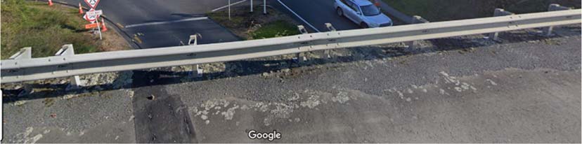
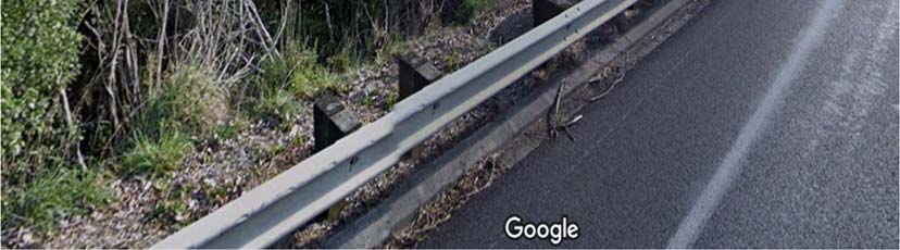
2.1.1 Existing median and roadside barriers
Moderate
The existing back-to-back semi-rigid median barrier and semi-rigid roadside barriers are likely to have been
produced and installed to NCHRP 350 TL-3 standards.
Act
Although the barriers appear not to have received any recent strikes (as would be evidenced by replaced
sections of barrier) their performance in preventing a vehicle (especially a high centre of gravity vehicle)
from crossing the median into opposing traffic or crashing into the gully or road below may be
questionable. The main concern is their low mounting height in relation to the road surface, particularly on
the interchange bridge.
Information
Official
the
Figure 2: Median barrier (Google, 2021)
under
Released
Figure 3: Bridge barrier (Google, 2021)
26 October 2021 │ Status: Final │ Project No.: 310201124 Child No.: 100.0101906 │ Our ref: WEX 110 Tamahere Detail RSA - Designer RSE
Client Response (v2) (002)
Page 5
1982
Act
Figure 4: Roadside barriers across gully (Google, 2021)
Recommendation(s)
1. Replace the existing median and roadside barriers (and especially the bridge barriers) with a taller and
more appropriate level of performance barrier system.
Information
Frequency
Severity
Rating
Crashes are likely to be
Death or serious injury is
The safety concern is
infrequent
likely
moderate
Designer
Agree in general principles, though this is currently outside the scope of the work,
response
and would require some specialist bridge input into the affixing replacement barriers
to the bridge deck. We have sourced plans of the original bridge, and preliminary
advice is that concrete barriers would not be able to be placed without
Official
considerable strengthening of the bridge, and semi-rigid TL4 barrier (eg thribeam)
would be more likely to be the appropriate treatment.
The replaced roadside barriers would be at the same offset from the edgeline,
which is in the order of 2.0m – considerably less that the 3.0m RONS standard
the
elsewhere on the Waikato Expressway.
The median barrier currently existing with a 5. 0m grassed median (with the
exception of the bridge crossing itself), narrower than the desired minimum for wire
rope barrier medians. It is noted that the Hamilton Section terminates with a double
sided F shape concrete barrier TL4 height. A suitable treatment would likely be a
double sided semi rigid barrier until the median widens to the existing
Safety Engineer
Designer response is acknowledged. It is recommended to the client that all barriers
under
comment
including interchange bridge barrier be replaced thereby providing safety to road
users.
Client decision
This work is beyond the original scope of works and requires review.
If mitigation of the existing risk is required, impact on the WEX 110km/h project
(schedule, time, cost) to be approved and funding allocated.
Action taken
A scope change request has been developed identifying the risk with the
performance of the existing barriers and potential mitigation options. Date of
resolution tbc.
Released
26 October 2021 │ Status: Final │ Project No.: 310201124 Child No.: 100.0101906 │ Our ref: WEX 110 Tamahere Detail RSA - Designer RSE
Client Response (v2) (002)
Page 6
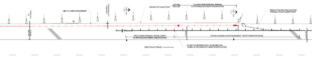
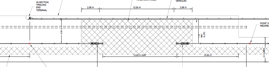
 2.1.2 Flexible to semi-rigid barrier transition detail
Comment
2.1.2 Flexible to semi-rigid barrier transition detail
Comment
The transition from flexible to semi-rigid barrier, which would be applied only near the northbound exit
ramp, shows a 1 m lateral step from the widened shoulder width of 3 m to tie into an existing shoulder
width of 2 m.
Normally the projected faces of the flexible barrier and the semi-rigid barrier would line up, i.e. be the
same offset from the edge line, and the flexible barrier would deviate behind the semi-rigid barrier only
locally.
1982
Act
3 m
2 m
Figure 5: Flexible to semi-rigid barrier transition detail
Although the proposed detail appears to adopt the same performance principles as shown in the RSB7A
standard drawing of Waka Kotahi, it may be worth checking that Waka Kotahi is comfortable with the
proposed detail.
Designer
Accepted. Propose to use a flared guardrail extension and terminal to widen to
Information
response
3.0m rather than a lateral step. Detail updated.
Safety Engineer
Agree with designer’s response.
comment
Client decision
Agree with SAT and RSE
Action taken
The design has been updated to reflect the designers response.
Official
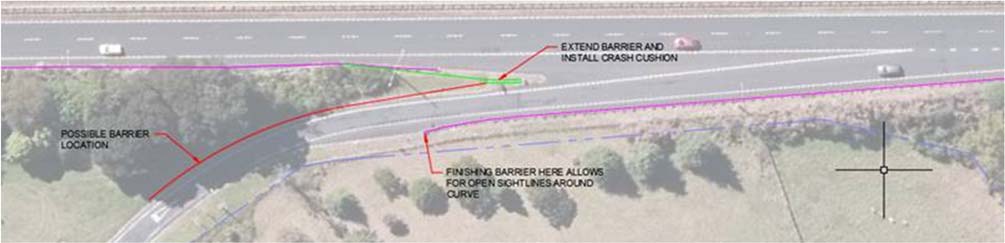
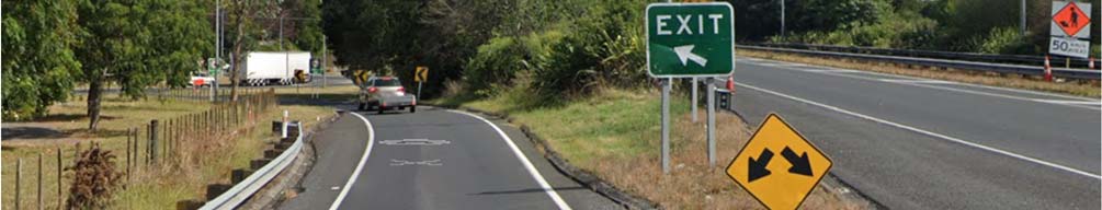
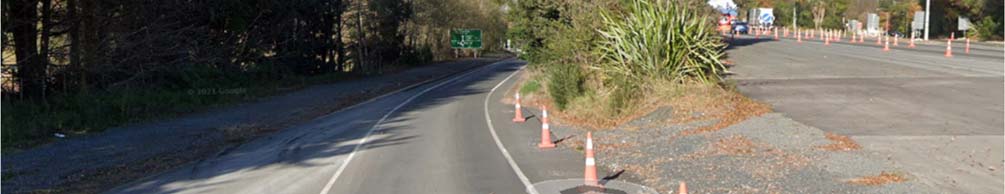
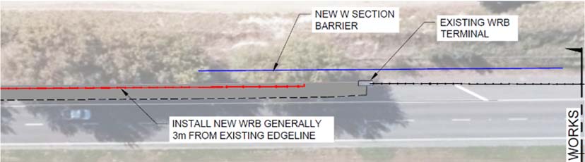
2.1.3 Proposed northbound exit ramp barriers
Comment
the
The designers are contemplating providing barriers along the right-hand side of the exit ramp and
connecting these to the existing barriers behind the nose with a crash cushion as indicated in Figure 6.
under
Figure 6: Proposed barriers along northbound exit ramp
Released
26 October 2021 │ Status: Final │ Project No.: 310201124 Child No.: 100.0101906 │ Our ref: WEX 110 Tamahere Detail RSA - Designer RSE
Client Response (v2) (002)
Page 7
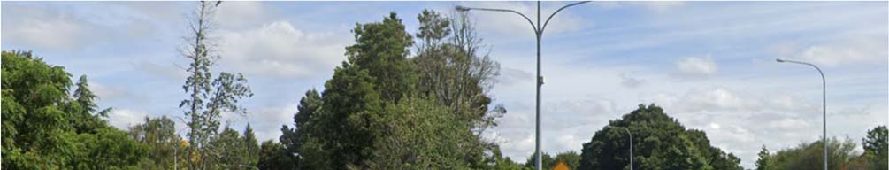
1982
Act
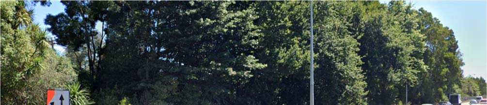
Figure 7: Trees and lighting column along northbound exit ramp (Google, 2021)
Information
The proposal would be a positive safety improvement as there are a number of large trees next to the
ramp in Figure 7.
Refer to Section 2.1.7 concerning the proximity of the lighting column in Figure 6 (yel ow circle) and Figure
7 to the proposed barrier and crash cushion.
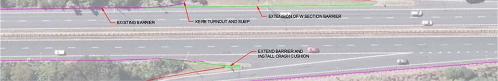
2.1.4 Proposed northbound entrance ramp barriers
Comment
Official
The designers are contemplating providing barriers along the left-hand side of the entrance ramp as
shown in red in Figure 8 and Figure 9 and extending the existing barriers to the nose as indicated by the
green line in Figure 8 and Figure 9. The southern end of the flexible barrier system already installed on the
the
Hamilton Bypass project is shown by the yellow arrow in Figure 9.
under
Figure 8: Proposed barriers along northbound entrance ramp
Released
26 October 2021 │ Status: Final │ Project No.: 310201124 Child No.: 100.0101906 │ Our ref: WEX 110 Tamahere Detail RSA - Designer RSE
Client Response (v2) (002)
Page 8
1982
Act
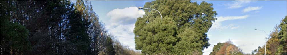
Figure 9: Trees and lighting column along northbound entrance ramp (Google, 2021)
The proposal would be a positive safety improvement as there are a number of large trees and a lighting
column next to the ramp.
The ramp joins the expressway as a lane gain so intervisibility between drivers entering the expressway and
drivers using the expressway should not be a significant factor.
Refer to Section 2.1.7 concerning the proximity of the lighting column in Figure 8 (yel ow circle) and Figure
Information
9 to the proposed barrier next to the expressway.
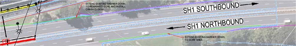
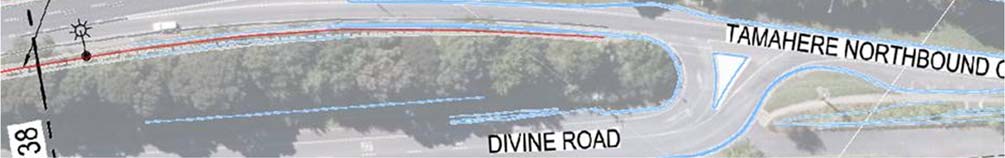
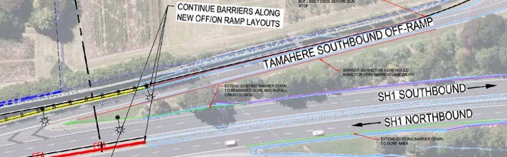
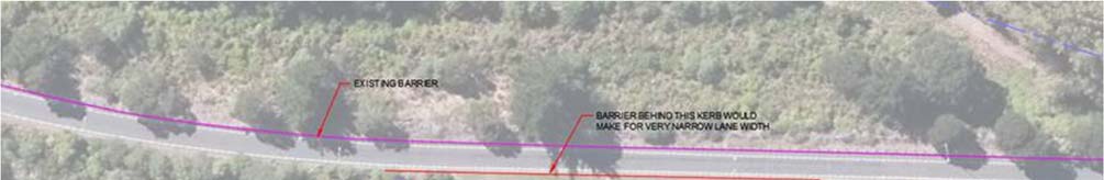
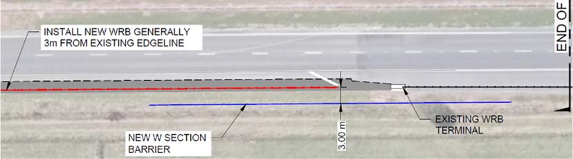
2.1.5 Proposed southbound exit ramp barriers
Comment
The designers are contemplating providing barriers along both sides of the entrance ramp as shown in red
in Figure 10 and extending the existing barriers to the nose as indicated by the green line in Figure 10.
Official
the
under
Figure 10: Proposed barriers along southbound exit ramp
Released
26 October 2021 │ Status: Final │ Project No.: 310201124 Child No.: 100.0101906 │ Our ref: WEX 110 Tamahere Detail RSA - Designer RSE
Client Response (v2) (002)
Page 9
1982
Act
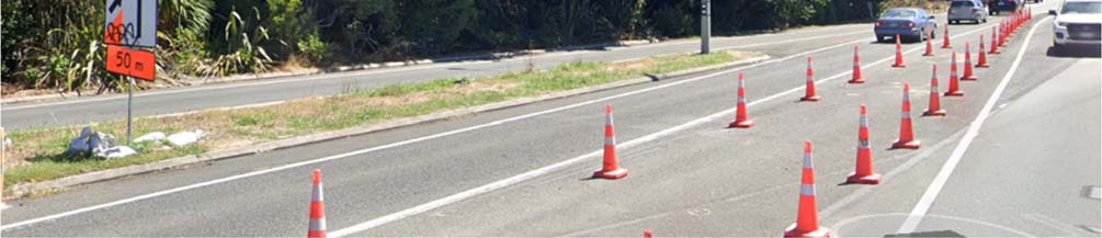
Figure 11: Trees and lighting column along southbound exit ramp (Google, 2021)
Information
The proposal would be a positive safety improvement as there are a number of large trees next to the
ramp.
However, the designers expressed concern that installing barriers along the exiting edge of seal on both
sides of the ramp would not provide enough width (5 m to 5.5 m) for broken down vehicles to stop or for
emergency vehicles to pass without significant widening of the pavement.
The barriers on both sides of the ramp probably do not need to be extended as far down the ramp as
Official
proposed. The is a farm gate about halfway down the ramp, to which access would need to be
maintained. the barriers could probably end at the gate. The ramp is straight and has good sight distance
along it. Speeds would be bleeding off as drivers slowed for the ramp terminal intersection. The greatest
risk of a crash would be close to the nose where drivers might suddenly realize that they have reached the
the
exit and swerve across the gore losing control and crashing into the trees on either side of the ramp.
If the decision to provide barriers or not is to be based on the need to widen the ramp, then it is suggested
that the left-hand barriers rather be set back beyond the existing kerbs close to the fence line than be
omitted. If the barriers were set back sufficiently from the kerb, the kerb should not be a factor provided
that the strip between the kerbs and the barrier were filled with hardfil . Again, it would be safer to provide
the barriers and accept a slight risk of less than perfect barrier performance, than to omit the barriers.
under
Refer to Section 2.1.7 concerning the proximity of the lighting column in Figure 10 (yel ow circle) and Figure
11 to the proposed barrier next to the expressway.
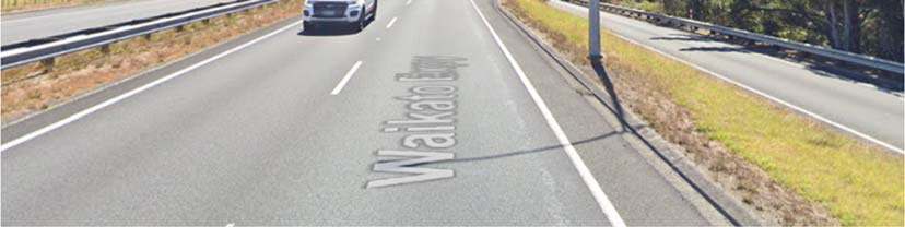
2.1.6 Proposed southbound entrance ramp barriers
Comment
The designers are contemplating providing barriers along both sides of the entrance ramp as shown in red
in Figure 12 and extending the existing barriers to the nose as indicated by the green line in Figure 12.
Released
26 October 2021 │ Status: Final │ Project No.: 310201124 Child No.: 100.0101906 │ Our ref: WEX 110 Tamahere Detail RSA - Designer RSE
Client Response (v2) (002)
Page 10
1982
Act
Figure 12: Proposed barriers along southbound entrance ramp
Information
Official
the
Figure 13: Lighting column near southbound entrance ramp merge
With the exception of the lighting column shown in Figure 13, there are no other significant hazards that
motorist need to be protected from in the vicinity of the merge area.
The ramp joins the expressway as a standard entrance ramp merge so intervisibility between drivers
entering the expressway and drivers using the expressway is a significant factor to be considered when
under
placing the barriers in a position that could obstruct the intervisibility.
Refer to Section 2.1.7 concerning the proximity of the lighting column in Figure 12 (yel ow circle) and Figure
13 to the proposed barrier next to the expressway.
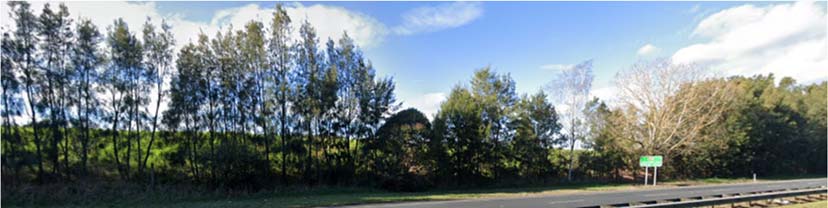
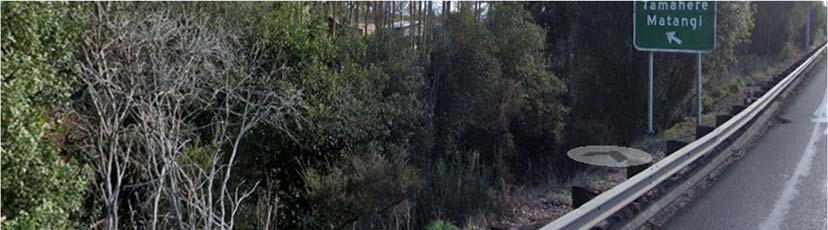
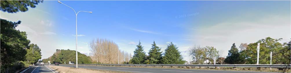
2.1.7 Lighting columns
Minor
Figure 14 shows a typical lighting column close to the edge of the expressway. Some, such as the one
arrowed in Figure 14 at the northbound exit ramp are behind existing barriers. Others, such as the one in
the foreground of Figure 14 at the southbound entrance ramp are currently exposed.
Released
The designers are contemplating extending the barriers on all four ramps up to the nose as described in
the preceding Sections 2.1.3, 2.1.4, 2.1.5, and 2.1.6. In all cases there one or more lighting columns that
would be within the operating zone of a barrier. The performance of the existing and proposed barriers,
and of the slip base lighting columns, would be unpredictable in a crash.
26 October 2021 │ Status: Final │ Project No.: 310201124 Child No.: 100.0101906 │ Our ref: WEX 110 Tamahere Detail RSA - Designer RSE
Client Response (v2) (002)
Page 11
1982
Act
Figure 14: Lighting column close to edge of expressway (Google, 2021)
It is acknowledged that the installation of the roadside barriers would be a safety improvement, even if
they were not installed in accordance with accepted normal operating clearances. However,
consideration should be given to mitigating the departure, like using a stiffer less deflective barrier system
or replacing the lighting columns with fewer high mast lighting columns in less vulnerable positions.
Recommendation(s)
Information
1. Mitigate the consequence of the potentially narrow gap between the lighting columns and the back
of the roadside barriers by using a stiffer less deflective barrier system.
2. In conjunction with the recommendation above, specify on the cross-section edge details what
minimum clearance between the lighting columns and the back of the barrier would be sought.
3. Where lighting columns might need to be relocated, specify ground-planted frangible lighting columns
to replace the slip-base columns.
Frequency
Severity
Rating
Official
Crashes are likely to be
Death or serious injury is
The safety concern is
occasional
unlikely
minor
Designer
Agreed, included in plan and details.
the
response
Safety Engineer
Acknowledge designer’s response. It is recommended to the client that slip base
comment
light columns are the preferred option. Clearance from the proposed barrier to all
light columns should be as per Waka Kotahi guidelines
Client decision
Agree with SAT and RSE.
However, M23 Appendix A, notes the below:
under
‘m) For new installations, lighting columns shall be installed so that there is at least
1.5 m clearance between the closest parts of the barrier system and the lighting
column. In retrofit situations only, this may be reduced to 1.0 m with application to,
and acceptance by, the Lead Safety Advisor. Lighting columns behind barriers
should not be on a frangible ‘slip base’ (for retrofit installations these should be
modified to reduce the risk of being activated by a deflecting barrier).’
Based on this requirement, ground-planted frangible lighting columns are to be
specified.
Released
Action taken
The design has been updated to ground-planted frangible lighting columns.
26 October 2021 │ Status: Final │ Project No.: 310201124 Child No.: 100.0101906 │ Our ref: WEX 110 Tamahere Detail RSA - Designer RSE
Client Response (v2) (002)
Page 12
 2.2
Maintenance Bays
2.2.1 Manoeuvring width
Moderate
2.2
Maintenance Bays
2.2.1 Manoeuvring width
Moderate
The proposed maintenance bays, which are intended to give access to the berm in both directions, are
shown in Figure 15 and Figure 16. Although the detail shows a width of 4 m, the layout indicates 3 m.
The designers explained that entry would be in the forward direction, as opposed to reversing into the bay.
1982
Act
Figure 15: Maintenance access bay detail
Information
Official
the
Figure 16: Proposed location of maintenance bays
The effective width of the maintenance bay in the detail in Figure 15would be less than the 4 m width
under
shown when the widths of the end terminals are taken into account. There is thus unlikely to be enough
width for a maintenance truck to manoeuvre into the maintenance bay from the shoulder and a portion
of the through lane will likely be required for the manoeuvre. Similarly, exiting the bay might require the
front of the vehicle to swing wide into the adjacent lane. This would mean blocking the through lane while
manoeuvring in or out, effectively bringing all traffic in that lane to an unexpected halt. This would be
unsafe, not only for the general traffic, but also for the maintenance personnel.
The proposal to reduce the width to 3 m, due to space constraints, could render the maintenance bay
almost unusable for any vehicle other than a ute.
The possibility of using a lane closure traffic management plan with attenuation vehicles was discussed in a
similar audit of the Hampton Downs section. However, the risk is that a maintenance person might try to
Released
use the bay not realising that it required a special temporary traffic management plan.
From a safety in design perspective, a driver trying to climb out of a vehicle is likely to stand on or fall over
the barriers, even if parked beyond the double barrier section as the available width for the maintenance
bay would still be limited by the road reserve boundary and cut or fill embankment.
26 October 2021 │ Status: Final │ Project No.: 310201124 Child No.: 100.0101906 │ Our ref: WEX 110 Tamahere Detail RSA - Designer RSE
Client Response (v2) (002)
Page 13
Furthermore, the gap in the roadside barrier will leave any worker of vehicle in the maintenance bay
exposed to the risk of a vehicle leaving the road at that point.
Recommendation(s)
1. Amend the design to a disengaging overlapping barrier layout that will allow maintenance vehicle
drivers to pull over onto the shoulder first and then access the maintenance bay without encroaching
into the adjacent through lane, while also fully shielding the maintenance vehicle and any personnel
in the maintenance bay. This may require additional access bays or alternative arrangements to
service the berm in both directions.
1982
Frequency
Severity
Rating
Crashes are likely to be
Death or serious injury is
The safety concern is
infrequent
likely
moderate
Act
Designer
The current location shown is the widest location within the project length. Tracking
response
paths with a 8m truck have been run on the current arrangement, which indicates
that an additional 5m of length is required for the vehicle to make the entry. Also we
acknowledge the difficultly exiting the vehicle, and have extended the paved area
of the maintenance bay 12m beyond the rear barrier terminal to enable a vehicle
to park clear of the barrier obstructing the doorway. Detail updated.
An alternate arrangement to ensure that the appropriate TMP is followed is to
remove the gap, and allow access into the bay area by means of a wire rope drop
in conjunction with the lane drop. This would al ow the rear barrier to be removed as
well.
Safety Engineer
Concern from SAT is noted, while it is preferable to have overlapping barriers , the
comment
option proposed by the designer also mitigates the risk highlighted by SAT. An
Information
alternate arrangement is not preferable. it is recommended to the client that the
arrangement proposed by designer be opted.
Client decision
Agree with Designer and RSE.
Action taken
The design has been amended to improve maintenance bay vehicle entry and
personnel exiting the vehicle within the maintenance bay.
Official
2.3
Road Signs and Markings
the
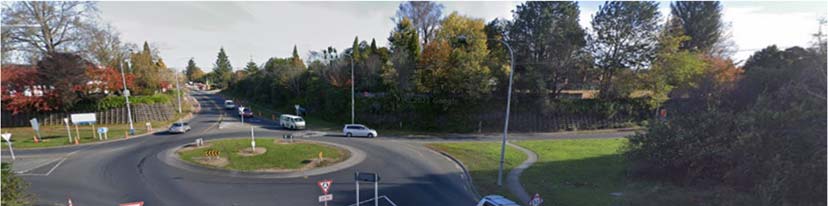
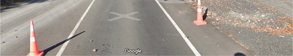
2.3.1 Gore signs and markings
Minor
The existing exit and entrance ramp gore areas have no hatching. Since there may now be crash cushions
on the exit noses, thus reducing the area on and behind the noses for recovery, both exit ramps would
benefit from increased visibility. It is acknowledged that the interchange is lit, but speeds will be higher.
All exit gores should be marked with diagonal chevron bars for consistency along the Waikato Expressway.
under
Te Kauwhata, Rangiriri and Huntly interchanges are marked, but interchanges such as Hampton Downs,
Ohinewai, and Tamahere are not.
The exit signs on the noses may need to be relocated to allow the crash cushions to be installed.
Recommendation(s)
1. Mark the exit and entrance gore areas with diagonal chevron bars. Apply this to all exits on the
Waikato Expressway for consistency.
2. Check if the exit signs need to be relocated behind the installed crash cushions.
Released
Frequency
Severity
Rating
Crashes are likely to be
Death or serious injury is
The safety concern is
infrequent
unlikely
minor
Designer
Agreed. Chevrons in the gore area of the southbound offramp are included in the
response
Hamilton Section plans. Hatching in northbound offramp has been added to the
drawings, and sign relocation provisionally included if necessary.
26 October 2021 │ Status: Final │ Project No.: 310201124 Child No.: 100.0101906 │ Our ref: WEX 110 Tamahere Detail RSA - Designer RSE
Client Response (v2) (002)
Page 14
Safety Engineer
Agree with designer’s response.
comment
Client decision
Agree with SAT and RSE.
Action taken
The design has been updated.
1982
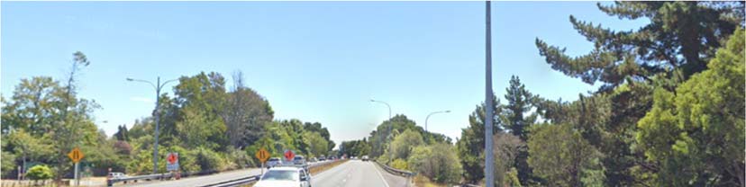
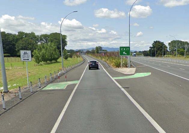
2.3.2 Cyclist signs and markings
Comment
Cyclists would still be allowed to use the 110 km/h sections of the Waikato Expressway.
Some sections of the existing Waikato Expressway cater for cyclists in the form of painted buffer strips (e.g.
Act
Rangiriri to Ohinewai) and signed crossing points across exit and entrance ramps as shown in Figure 17
which is in an existing 110 km/h speed limit zone along the Cambridge Bypass not far from the Tamahere
interchange. Such shoulder buffers and cyclist crossings are not present on the Hampton Downs section or
the Tamahere section or other recently opened sections such as the Huntly Bypass.
Information
Official
the
under
Figure 17: Exit ramp cyclist crossing at Cambridge (west) interchange (Google, 2019)
Since the Waikato Expressway looks like a motorway, it would be reasonable to assume that some drivers
would not expect to encounter cyclists in such an environment and would therefore not be looking out for
cyclists.
While the buffer strips and signed crossing points provide no physical protection for cyclists, the signs and
markings may remind drivers to be on the lookout for cyclists. The converse
may also be true—where the
signs and markings end or are not present, drivers may think that cyclists are not al owed on the
expressway.
Released
A consistent philosophical approach should be taken regarding the provision of cyclist signs and markings
along the entire length of the Waikato Expressway.
26 October 2021 │ Status: Final │ Project No.: 310201124 Child No.: 100.0101906 │ Our ref: WEX 110 Tamahere Detail RSA - Designer RSE
Client Response (v2) (002)
Page 15

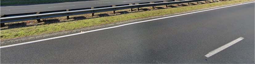
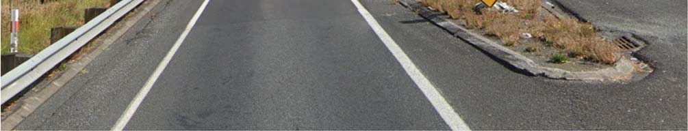
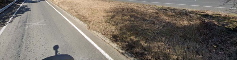
 2.3.3 RRPMs and ATP
Comment
2.3.3 RRPMs and ATP
Comment
The drawings do not indicate any change to the existing edge line markings, which do not include ATP but
do include RRPMs. For consistency along the Waikato Expressway a decision should be made to include
ATP along all sections, unless they could be annoying for people living close by.
The ATP markings applied on the recent Longswamp to Rangiriri project (June 2020) coincided with the
RRPMs. Not only did the application cover the RRPMs in many cases, but the raised portion of the ATP also
tended to mask the full effectiveness of the RRPM reflectivity, effectively reducing the RRPM to about half 1982
its reflective area when viewed from the low angle of a passenger vehicle.
Fortunately, it appears that the exiting RRPMs along the Tamahere section are set far enough away from
the existing edge line for ATP to be applied between the line of RRPs and the edge line. However, the
foregoing comment should be borne in mind when drawing up any specifications or drawings for ATP.
Act
Information
Official
Figure 18: Existing RRPM position in relation to edge line
the
under
Released
26 October 2021 │ Status: Final │ Project No.: 310201124 Child No.: 100.0101906 │ Our ref: WEX 110 Tamahere Detail RSA - Designer RSE
Client Response (v2) (002)
Page 16


3
Audit Statement
We declare that we remain independent of the design team and have not been influenced in any way by
any party during this road safety audit.
We certify that we have used the available plans, and have examined the specified roads and their
environment, to identify features of the project we have been asked to look at that could be changed,
removed, or modified in order to improve safety.
We have noted the safety concerns that have been evident in this audit and have made
recommendations that may be used to assist in improving safety.
1982
s 9(2)(a)
Signed
Date 22 October 2021 Act
s 9(2)(a)
Technical Director – Roads and Highways, Stantec
s 9(2)(a)
Signed
Date 26 October 2021
s 9(2)(a)
Project Transportation Engineer, Stantec
Information
Signed
Date 26 October 2021
Heather Liew, BEng(Hons), MET
Safety Engineer, Waka Kotahi
Official
the
under
Released
26 October 2021 │ Status: Final │ Project No.: 310201124 Child No.: 100.0101906 │ Our ref: WEX 110 Tamahere Detail RSA - Designer RSE
Client Response (v2) (002)
Page 17


4
Response and Decision Statements
System designers and the people who use the roads must all share responsibility for creating a road system
where crash forces do not result in death or serious injury.
4.1
Designer’s Responses
I have studied and considered the auditors’ safety concerns and recommendations for safety
improvements set out in this road safety audit report and I have responded accordingly to each safety
concern with the most appropriate and practical solutions and actions, which are to be considered further
1982
by the safety engineer (if applicable) and project manager.
s 9(2)(a)
Act
Signed
Date 17/02/2022
s 9(2)(a)
4.2
Safety Engineer’s Comments (if applicable)
I have studied and considered the auditors’ safety concerns and recommendations for safety
improvements set out in this road safety audit report together with the designer’s responses. Where
appropriate, I have added comments to be taken into consideration by the project manager when
deciding on the action to be taken.
s 9(2)(a)
Information
Signed
Date 01/03/2022
s 9(2)(a)
4.3
Project Manager’s Decisions
Official
I have studied and considered the auditors’ safety concerns and recommendations for safety
improvements set out in this road safety audit report, together with the designer’s responses and the
comments of the safety engineer (if applicable) and having been guided by the auditor’s ranking of
concerns have decided the most appropriate and practical action to be taken to address each of the
the
safety concerns.
Signed
Date 02/02/2022
[Shane Small, BEng(Civil), Project Manager, NZTA]
under
4.4
Designer’s Statement
I certify that the project manager’s decisions and directions for action to be taken to improve safety for
each of the safety concerns have been carried out.
s 9(2)(a)
Signed
Date 17/02/2022
Released
s 9(2)(a)
4.5
Safety Audit Close Out
The project manager is to distribute the audit report incorporating the decisions to the designer, safety
audit team leader, safety engineer, and project file.
Date:……………………………….
26 October 2021 │ Status: Final │ Project No.: 310201124 Child No.: 100.0101906 │ Our ref: WEX 110 Tamahere Detail RSA - Designer RSE
Client Response (v2) (002)
Page 18
1982
Act
Information
Official
the
under
Released
26 October 2021 │ Status: Final │ Project No.: 310201124 Child No.: 100.0101906 │ Our ref: WEX 110 Tamahere Detail RSA - Designer RSE
Client Response (v2) (002)
Page 19
5
References
Google. (2019, December). Street View.
Google. (2021, May). Street View.
Google. (2021, February). Street View.
1982
Act
Information
Official
the
under
Released
26 October 2021 │ Status: Final │ Project No.: 310201124 Child No.: 100.0101906 │ Our ref: WEX 110 Tamahere Detail RSA - Designer RSE
Client Response (v2) (002)
Page 20
 Auckland
Level 3 Stantec House, 111 Carlton Gore Road
Newmarket, Auckland 1023
PO Box 13-052, Armagh
Christchurch 8141
Tel +64 9 580 4500
1982
Please visit
www.stantec.com to learn more about how
Stantec design with community in mind.
Act
Information
Official
the
under
Released