 Reference Guide
T3A2-rg
Type 3 MANAct
T3 001-
Information
Official
the
under
Released
Status of this document
This document is issued by the New Zealand Fire Service.
Recommendations for change: Training encourages and welcomes feedback on all our materials.
Recommendations for changes to this material should be sent to Training using the
Training Feedback Form on FireNet. You will find it under Training Information in the
Act
Training section of FireNet.
For the most up-to-date information, please refer to FireNet.
Document title: Type 3 MAN NZFS T3 001- Reference Guide
Published: December 2014
Amended: March 2015, June 2015, August 2015,
September 2015, April 2016, May 2016
© New Zealand Fire Service – Training
Information
If you wish to copy or reproduce any of the material in this document, please contact:
Team Leader, Learning and Development
Training
PO Box 2133
Wellington 6140
Official
the
under
Released
New Zealand Fire Service | Training
link to page 5 link to page 5 link to page 5 link to page 5 link to page 6 link to page 6 link to page 7 link to page 8 link to page 8 link to page 8 link to page 8 link to page 8 link to page 8 link to page 8 link to page 8 link to page 8 link to page 9 link to page 9 link to page 9 link to page 9 link to page 9 link to page 10 link to page 10 link to page 10 link to page 12 link to page 14 link to page 14 link to page 14 link to page 15 link to page 16 link to page 16 link to page 16 link to page 17 link to page 17 link to page 17 link to page 18 link to page 19 link to page 20 link to page 20 link to page 22 link to page 22 link to page 22 link to page 23 link to page 25 link to page 26 link to page 26 link to page 27
iii
Contents
Introduction 1
Purpose of this reference guide
1
Training requirements
1
Appliance identification
1
Section 1: Overview of the appliance
2
References 2
Appliance views
3
Section 2: Appliance details
4
Act
Cab and chassis
4
Body 4
Water tank
4
Main pump
4
High pressure pump
4
Monitor and base
4
Weights
4
Travel height
4
Length 5
Width 5
Tyres
5
Transmission 5
Information
Engine 5
Section 3: Appliance cab
6
Cab layout
6
Dash layout and functions
6
Siren and public address system (PA)
8
Battery and battery isolator
10
Official
10
230 volt inlet and indicator light
10
Battery charger
11
the
Section 4: General safety
12
Employer responsibilities
12
Driving safety - general
12
Section 5: Driving
13
Oil and water levels
13
Adjusting the steering wheel
13
under
Seat adjustments
14
Instrument panel
15
Running gear
16
Retarder and Brakematic systems
16
Anti-lock Braking System (ABS)
18
ASR (anti spin regulator) and ESP
(electronic stability programme) switch
18
Electronic stability programme (ESP)
19
Parking brake
21
Released
Starting the engine
22
Gear selection
22
Differential locks
23
May 2016 | Version 7
link to page 28 link to page 28 link to page 28 link to page 29 link to page 30 link to page 31 link to page 31 link to page 31 link to page 32 link to page 33 link to page 34 link to page 35 link to page 35 link to page 35 link to page 36 link to page 37 link to page 38 link to page 38 link to page 39 link to page 39 link to page 39 link to page 40
iv
Type 3 MAN T3 001- Reference Guide
Section 6: Water pumps
24
Main pump unit
24
Hosereel pump
24
Water Dragon
25
Tank refill
26
Overflows, relief valve and total pressure master system 27
Total pressure master system (TPM)
27
Pump controls and instrument panel
27
Pump engagement
28
Act
Pump disengagement
29
Hosereels 30
Section 7: Foam system
31
Foam Pro system
31
Foam tank
31
Foam Pro operation
32
Getting to work with foam
33
High / Low flow warning
34
Refilling the foam concentrate tank
34
Section 8: Equipment
35
Crossfire monitors and Safe-Tak 125 portable base
35
Information
Ladders 35
Section 9: Lighting
36
Official
the
under
Released
New Zealand Fire Service | Training
1
Introduction
Purpose of this reference guide
This reference guide is designed to prepare you, as appropriate to your
role, to drive, operate and crew the Type 3 appliance in a safe and
efficient way.
This reference guide covers the basic information required to operate
this appliance. This reference guide and the associated training do not
replace specific driver, pump operator, and firefighter training.
Act
Training requirements
Before the vehicle can be operational at your station, all crew members
must:
• self-study using this reference guide
• familiarise themselves with the vehicle, as appropriate to their role
Information
• complete the Type 3 MAN NZFS T3 001 Familiarisation Checklist.
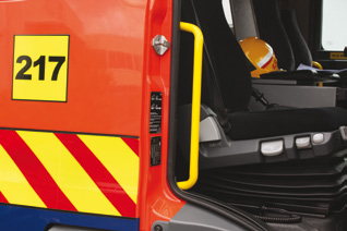
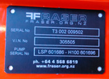
Appliance identification
Each Type 3 MAN appliance has a New Zealand Fire Service
identification number. This number is part of a sequential list (T3 001,
Official
T3 002, T3 003, etc.). It enables you to ensure this is the correct
reference guide for your specific vehicle. The identification number is
on the plate inside the driver’s door, next to the Fraser Fire and Rescue
ID.
the
under
Released
NZFS Identification number
May 2016 | Version 7
2
Section 1: Overview of the appliance
References
Policies
Policy and Operational Instructions that apply:
The driving of New Zealand Fire Service (NZFS) appliances is covered
by policy FL1-1 Driving Operational Vehicles. FL1-1 should be
reviewed by all drivers and officers as part of your training.
Act
FL1-1 is available on FireNet.
FL1-1 provides instructions for driving NZFS operational vehicles, and
includes information on safety requirements.
Manufacturers’ manuals
Type 3 Appliance manufacturer’s manual
This manual contains the manufacturer’s specific information regarding
operator use and servicing details for the major components of the
appliance. Each appliance is issued with a manual on entering service; Information
Fraser Fire and Rescue produce this manual.
Fraser Fire and Rescue operational and maintenance
manual
This manual contains general information:
Official
• operating procedure
• general information
the
• routine checks.
MAN Owner’s Manual
This manual contains information specific to the factory cab, chassis
and driveline components of the appliance.
under
It tells you what you need to know about the vehicle to be able to drive
it without risking damage to the vehicle or injury to yourself.
Darley LSP 1000 And HD 100 Operational and
Maintenance Manual
This manual contains information specific to the pump:
Released
• operating procedure
• preventative maintenance
• trouble shooting
• corrective maintenance.
New Zealand Fire Service | Training
3
Section 1: Overview of the appliance
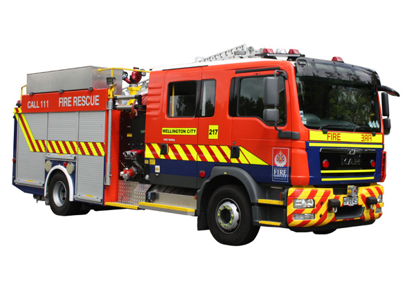
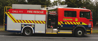
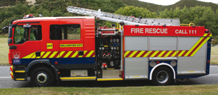
Appliance views
Full details of the major components can be found in the respective sections of this reference manual.
Act
Off-side view
Information
Official
the
Near-side view
under
Released
May 2016 | Version 7
4
Section 2: Appliance details
Cab and chassis
MAN TGM 290HP 4 x 2 BL Crew Cab fitted with Fraser BA seats.
• 4 x 2
• single steer front axle with conventional tyres
• air bag rear suspension height switch on the dash
Act
• cruise control
• electronic speed limiter.
• electronic stability programme (ESP)
• ABS braking.
Body
Information
The body is constructed from marine-grade aluminium and fitted with
Fraser Fire and Rescue doors.
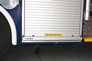
The maximum allowable weight for each locker is marked on the locker
door catch.
Official
Water tank
1450 litre capacity
the
Main pump
Darley LSP1000 Midship PTO driven
under
High pressure pump
Darley HD100 PTO driven
Monitor and base
TFT Crossfire with Safe-Tak 1250 Portable base
Released
Weights
Operational weight: 13 000 kg
Travel height
3.2 metres
New Zealand Fire Service | Training
5
Section 2: Appliance details
Length
8.5 metres
Width
2.5 metres
Act
Tyres
Front
Size
- Continental 305/70R 19.5
Pressure - 770 kPa
Rear
Size
- Continental 305/70R 19.5
Information
Pressure - 570 kPa
Transmission
ZF 5 HP automatic 5 speed transmission with an integrated retarder
Official
Engine
MAN 6 cylinder inline, turbo charged, Intercooler, 290 HP at 2300 rpm
the
under
Released
May 2016 | Version 7
6
Section 3: Appliance cab
Cab layout
The following diagrams show only those controls/switches and
warning lights pertinent to the operation of the appliance. Full details
NOTE
of factory Man cab layout can be found in the Man Operator’s Manual.
Do not drill holes into the
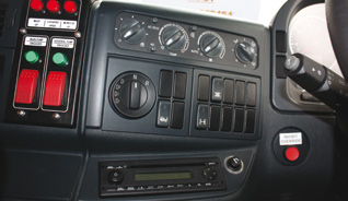
Dash layout and functions
cab or modify in any way.Act
Controls – left of steering column
1
2
Information
3
Official
the
6
5
4
1. Climate controls
2. Wipers and window washers
under
3. Inhibit override
4. Anti spin regulator
5. Diff lock
6. Rear suspension lowering
Released
New Zealand Fire Service | Training
7
Section 3: Appliance cab
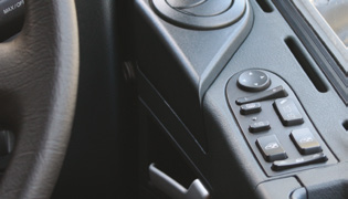
Controls – right of steering column
1
2
3
Act
4
5
1. Adjust mirror
8
7
6
Information
2. Select the mirror on the left or right of the vehicle
3. Selects mirror to adjust
4. Switch mirror heater on and off
Official
5. Check lamp comes on when mirror heater is activated
6. Central locking
the
7. Window raise/lower switch
8. Move the main mirror out briefly
under
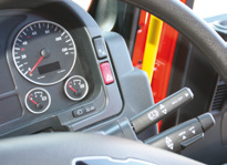
1
2
3
4
Released
1. Fog lamp
2. Hazard light
3. Retarder control stalk
4. Brakemmatic, cruise control and road speed limiter stalk
May 2016 | Version 7
8
Type 3 MAN T3 001- Reference Guide
Act
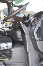
Grille release.
This catch unlocks the grille. A second
catch at the bottom centre of the grille
needs to be released when you lift
the grille (same process as most car
bonnets).
Information
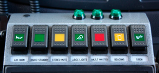
Siren and public address system
(PA)
Official
The siren is operated from the cab control console. To operate the
siren, the beacons must be on.
the
under
Emergency response
Beacons
Siren
air horn
Released
New Zealand Fire Service | Training
9
Section 3: Appliance cab
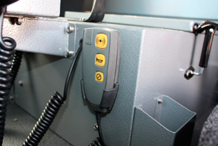
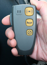
The siren tones are operated from the siren control hand piece which is
located on the officer’s side of the storage compartment.
Siren control
Push to
Siren
hand piece
talk (PTT)
Microphone
tones
Act
Information
Official
To use the PA, the beacons must be switched on. Note: the siren
does not need to be on. If the siren is in use, the PA can also be used.
In this case, the PA will override the siren while you are talking. The
siren will resume once you have finished talking.
the
Press the PTT button to activate the public address function.
The PA volume is displayed any time the PTT button is depressed, as
shown below.
under
Level 1
Level 2
Level 3
Level 5
(min)
(max)
Released
+
Increase PA volume
+
Decrease PA volume
May 2016 | Version 7
10
Type 3 MAN T3 001- Reference Guide
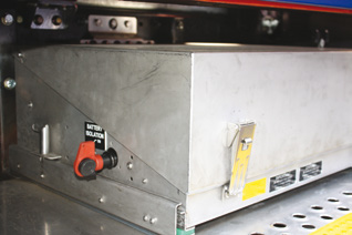
Battery and battery isolator
Act
Batteries
Information
Battery isolation switch
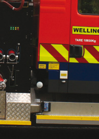
230 volt inlet and indicator light
Official
the
under
230 volt inlet
Released
New Zealand Fire Service | Training
11
Section 3: Appliance cab
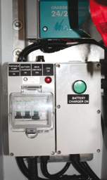
Battery charger
The battery charger is mounted on the rear wall behind the number 4
seat.
Act
Portable pump
battery charger
indicator light
Information
Official
If the indicator light below the 230 volt inlet is not illuminated, it
indicates no power to the appliance charger. Check the circuit breaker
beside the charger and in the engine house.the
The charger is fully automatic. To switch it on, press the power switch
and hold for three seconds. The power switch will illuminate green.
Once switched on, the charger automatically resumes operation when
NOTE
reconnected to the 230 volt supply.
under
On the left hand side of the steering wheel is a 230-volt inhibitor
When the vehicle is plugged
override. The vehicle cannot be started while the vehicle is connected
in correctly, the green light
to the 230-volt supply. In the unlikely event of relay failure or the
below the cab inlet plug will
vehicle needing to be started with the 230 volt connected, the red
light up after 15 seconds.
knob on the left hand side of the steering wheel labelled ‘inhibit
override’ can be pushed, allowing the vehicle to be started. Under
normal conditions this is not required.
Released
May 2016 | Version 7
12
Section 4: General safety
Employer responsibilities
Employers must ensure:
• the appliance is operated by competent operators and is used in
accordance with the operating instructions
• appropriate documentation and records are maintained
Act
• the appliance is inspected regularly, repaired and maintained by
those competent to carry out such work and that periodic testing is
carried out.
Driving safety - general
Overview
The following notes are general safety notes pertaining to this
Information
appliance they are not intended to fulfil the requirements of the
Emergency Response Driver training for this appliance.
Pre-driving checks
NOTE
Before starting road transportation:
Official
• complete the standard Career appliance daily checklist (FL7 FML)
The Career appliance
• check:
daily checklist FL7 FML is
available on FireNet.
the
– all equipment in lockers is stowed correctly
– all lockers are closed
– the monitor and light masts are housed.
under
Vehicle braking warning
Due to the weight of this vehicle, drivers must take care when braking
and ensure the vehicle is driven to the road and weather conditions.
Released
New Zealand Fire Service | Training
13
Section 5: Driving
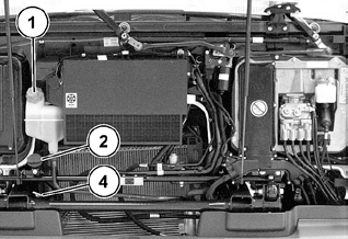
Oil and water levels
Act
3
Information
1. Filler neck for coolant
2. Filler neck for engine oil
3. Dipstick for engine oil
Official
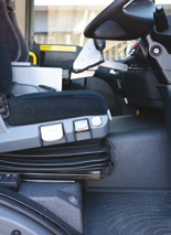
Adjusting the steering wheel
the
1. Press and hold the push button
on the driver’s seat console
with your heel.
2. Set the rake and reach of the
steering wheel.
under
3. Release pushbutton again. The
steering wheel locks into place.
Released
Steering wheel
adjuster
May 2016 | Version 7
14
Type 3 MAN T3 001- Reference Guide
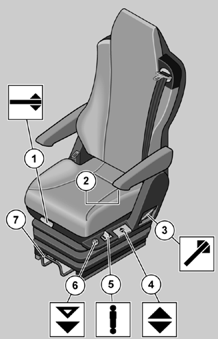
Seat adjustments
Act
Information
Official
the
under
1. Seat surface angle
Released
2. Arm rests
3. Backrest angle
4. Seat surface height
5. Vertical damper adjustment
6. Quick lower - for getting in and out
7. Whole seat backwards and forwards
New Zealand Fire Service | Training
15
Section 5: Driving
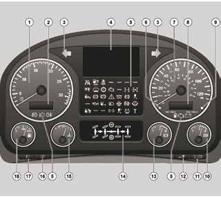
Instrument panel
Act
Information
Official
1. Rev counter
NOTE
2. Outside temperature
– black ice warning
the
– total mileage
For more information on
the instrument panel, refer
3. Turn indicators, tractor
to pages 40-41 of the Man
Operator’s Manual.
4. Display
under
5. Check lamps
6. Sensor for automatically adjusting brightness of the instrument
lighting and the EU monitoring device display
7. Speedometer
8. Time
trip counter
Released
speed
9. Warning speed
10. Reservoir pressure in brake circuit
11. Information messages on display
trip odometer or speed
vehicle menu
May 2016 | Version 7

16
Type 3 MAN T3 001- Reference Guide
12. Information messages on display
vehicle menu
NOTE
13. Reservoir pressure in brake circuit
14. Differential locks
Do not accelerate and brake
at the same time the exhaust
15. Coolant temperature
brake is engaged. Doing so
could cause damage by over
Act
16. Instrument lighting
pressurising the engine.
17. Select language
18. Fuel level
Running gear
Lowering rear suspension
Information
Press to lower the rear of the
body from drive height to a kneel
position. This will lower the rear
of the appliance by 150 mm to
assist with the removal of the
ladder from the gantry.
Official
Press again to return the rear of
the body to drive height.
the
If the rear of the appliance is
in the kneel position when the
appliance is driven at 5 km per
hour the appliance automatically
returns to the drive height. under
Retarder and Brakematic systems
The MAN appliance has two braking systems: foot brakes, and a
Released
transmission retarder.
These automatically combine when the Brakematic function is
activated when travelling down hill.
The appliance computer will automatically decide which system, or
a combination of both systems, to use to hold the appliance at the
selected speed. The Brakematic system is not cruise control.
New Zealand Fire Service | Training
17
Section 5: Driving
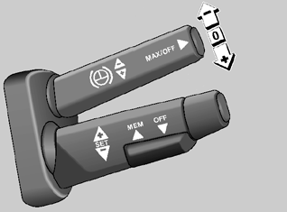
Retarder control stalk
MAX/OFF button
Act
Cruise control stalk
Information
Retarder and Brakematic controls
Retarder
The retarder is a hydraulic brake driven by the transmission output
Official
shaft. It is used to supplement the foot-brake system and also to
NOTE
control downhill speed. There are three levels of braking, from low
braking (level 1) to maximum braking (level 3).
the
The retarder is fully integrated with the brake pedal. The driver does
There is no need to turn
not need to use the retarder stalk on the steering column to engage the
the retarder off for wet
retarder.
surfaces. The ESP system
has overall control over the
The first 25% of the brake pedal travel is mainly retarder, but the
braking system including the
service brake will come on initially as the retarder takes a second or
retarder and will take over in
under
two to build up pressure. Once the retarder is up to pressure it takes
any situation it deems to be
over the braking. As the brake pedal is depressed towards 25% of it’s
unsafe.
travel the service brake starts to work and increases smoothly as more
foot brake is applied.
Under heavy braking both the service brakes and 100% retarder are
working together. The retarder symbol will appear on the instrument
panel but there will not be a number with it.
Released
The stalk also operates the retarder, it has 3 positions. Position 1
selects 40% retarder, position 2 selects 70% retarder and position
3 selects 100% retarder. The button at the end of the stalk sets the
retarder to 100%.
You might find the stalk to be a more suitable control for cruising down
long descents.
May 2016 | Version 7
18
Type 3 MAN T3 001- Reference Guide
–
MAN Brakematic
The Brakematic system is primarily for downhill use. When the system
is engaged, it will keep the vehicle travelling at the speed selected by
NOTE
the driver by automatically using the retarder and foot brakes.
Act
To engage:
When adjusting the speed
setting, the Brakematic will
momentarily disengage then
1. Set the required downhill speed by applying the foot brake for a
reengage at the new speed.
minimum of three seconds.
2. Switch on the MAN Brakematic system using the rocker switch on
the Cruise Control stalk (MEM/OFF).
The MAN Brakematic is now engaged and will maintain the vehicle at
the current speed.
Information
Depressing the brake pedal will temporarily override the system.
Releasing the brake pedal will reengage the Brakematic system at the
new speed.
To disengage:
Official
Depress the accelerator.
Anti-lock Braking System (ABS)
the
The ABS compares the speed of each wheel and adapts braking
power accordingly so that no wheels lock up.
The advantages of ABS are:under
• shortest possible stopping distances without loss of steering and
directional stability
• higher degree of control on slippery surfaces
• reduced tyre wear.
SAFETY NOTE
ASR (anti spin regulator) and ESP
Released
(electronic stability programme)
When the ASR/ESP is
deactivated the vehicle is
switch
less safe, as there is no
automatic intervention by the
brake system.
Only deactivate this system if off road. On other road surfaces, the
ASR/ESP system must be activated.
Drive to the conditions at all
times.
New Zealand Fire Service | Training
19
Section 5: Driving
Electronic stability programme (ESP)
ESP is a safety system that assists the driver in critical situations, for
example:
• skidding (over steer and under steer)
• risk of overturning
Act
by
• improving the ability to control and steer the vehicle
• reducing the risk of overturning.
The ESP system includes sensors that measure the stability of the
appliance.
The ESP system is connected to the braking and engine management
systems and possesses two vehicle-stabilising sub-functions. One of Information
these is mainly active when adhesion values are low to medium, and
helps to counteract over steer and under steer. The other sub-function
mainly takes effect when adhesion is moderate to high, and reduces
the risk of overturning. The two sub-functions are linked via an
interface and operate together. The ESP check lamp on the instrument
panel screen flashes yellow when ESP is active.
Official
ESP directional stabilising
ESP keeps the vehicle stable over surfaces with low or moderate
the
adhesion, provided that the dynamic limits are not exceeded. It
counteracts the tendency to over or under steer in certain situations.
In these situations the ESP will apply the brakes to individual wheels
to correct the behaviour of the vehicle. The ABS system will ensure
wheel lock up is prevented. under
ESP to reduce the risk of overturning
This function is intended to prevent the vehicle from overturning in
certain situations (subject to being driven within the dynamic limits
imposed by the laws of physics). This function is mainly needed at
moderate to high levels of road grip.
ESP performs this function in two stages:
Released
1. The first stage reduces the vehicle’s road speed until lateral
acceleration is below the critical level at which overturning could
occur.
May 2016 | Version 7
20
Type 3 MAN T3 001- Reference Guide
2. In the second stage, any wheel which leaves the road surface on
the vehicle is detected. If a vehicle wheel lifts away from the road
surface, the second ESP stage applies all the vehicle’s brakes. The
ABS system will ensure wheel lock up is prevented.
Act
Information
Official
the
under
Released
New Zealand Fire Service | Training
21
Section 5: Driving
Parking brake
To apply the park brake, push the lever backwards until it engages.
Act
Park brake lever
Information
Air tank drain
The air tank drain is on the offside, below the A locker.
Official
the
under
Released
Air tank drain
May 2016 | Version 7
22
Type 3 MAN T3 001- Reference Guide
Starting the engine
To start:
• depress the brake pedal.
• put the vehicle in neutral
• turn the ignition key until the glow-plug symbol shows
Act
• when “START ENGINE” is displayed, turn the ignition key fully.
If the engine doesn’t start, check the battery master switch is on.
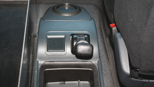
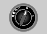
Gear selection
Automatic transmission
Information
Official
Modes
the
The following ZF 5 HP automatic transmission modes can be selected
with the mode switch:
• ‘D’. Drive forwards, unrestricted mode
Start off in 1st gear, automatic upshifts up to 5th gear.
under
• ‘D1’, ‘D2’, ‘D3’. Drive forwards, restricted mode
– ‘D3’. Start off in 1st gear, automatic upshifts up to 3rd gear
– ‘D2’. Start off in 1st gear, automatic upshifts to 2nd gear.
– ‘D1’. Start off in 1st gear – no upshifts
Released
– ‘R’. Drive reverse.
New Zealand Fire Service | Training
23
Section 5: Driving
Changing modes
When changing modes from drive to reverse or back:
NOTE
1. Ensure the vehicle is stationary.
2. Place your foot hard on the brake pedal.
Important:
3. Move the selector from drive to neutral, pause briefly, move to
Do not change from drive Act
reverse.
straight across to reverse.
The transmission will not
The process is the same for going from reverse to drive.
engage the selected mode.
Differential locks
To clear, place the selector
in neutral and wait five
seconds and re-select mode.
The appliance is fitted with a differential lock. Only engage the
differential lock when traction is lost and the vehicle is travelling in a
straight line at a speed of less than 7 km/hr.
Information
As soon as the appliance returns to hard standing, the diff lock must
be disengaged. Damage can occur to the drive axles if the differential
lock is left activated and driven on a normal road surface.
Official
the
under
Released
May 2016 | Version 7

24
Section 6: Water pumps
Main pump unit
The Darley pump unit is mounted on the pump frame and is PTO
driven.
SAFETY NOTE
There are two important output ratings, one for normal firefighting use
When using the water pump,
with low pressure deliveries, and the other relevant to acting as a base
always use Class 2 hearing
pump for aerial appliances.
protection.
Act
1. 3840 litres per minute @ 1050 kPa
2. 3600 litres per minute @1500 kPa - through delivery outlets to an
aerial
Hosereel pump
The Darley pump unit obtains its power from the vehicle’s PTO. The
hose reel pump is mounted on the nearside lower section of the pump
frame. This unit is controlled from the main pump panel by the same
Information
electronic hand throttle that controls the main pump.
Official
the
Hosereel rewind
under
Released
New Zealand Fire Service | Training
25
Section 6: Water pumps
The hose reel pump is fed by the main pump. Both must be running
when using the hose reels.
When using the hose reels from the tank, it is recommended you prime
the pump after opening the tank-to-pump valve to evacuate the air
from inside the pump.
The hosereel system is designed to provide 440 litres per minute @
2400 kPa. At this setting the main pump pressure will be 1050 kPa.
Act
Water Dragon
To operate the water dragon set the hose reel pump pressure to 2400
kPpa. This will provide 1500 l/m @ 1050 kPa from the main pump to
deliveries.
Information
Official
the
under
Released
May 2016 | Version 7

26
Type 3 MAN T3 001- Reference Guide
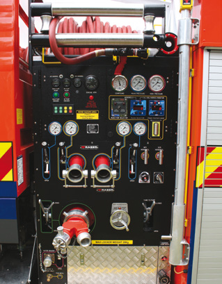
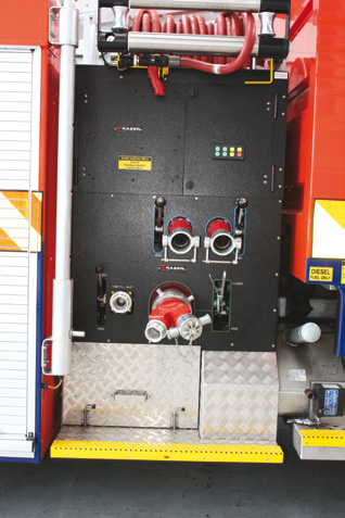
Offside pump panel
Act
Information
Hosereel rewind
Official
the
under
Tank refill Tank refill inlet
Released
The tank refill inlet bypasses the pump and feeds directly into the tank
for manually filling the tank. The main purpose of this feature is to allow
the tank to be refilled while draughting by connecting a delivery outlet
to the direct tank fill with standard hose.
There is no tank refilling capability on the roof.
New Zealand Fire Service | Training
27
Section 6: Water pumps
Overflows, relief valve and total
pressure master system
The overflow from the water tank is piped to ground and is behind the
rear axle. The cooling lines are piped to the water tank, so will dump
water to ground through the water tank overflow when the water tank
is full.
Act
The suction relief valves (one each side of the vehicle) are preset to
1150 kPa. They are designed to protect the supply line into the pump.
The suction relief valves are fitted between the collector head and the
intake valve. In the event of high intake pressure, the relief valve opens
and the excess water dumps to ground below the pump panel on each
side.
The high pressure pump has a preset (kunkle) pressure relief valve,
which has been set to 4200 kPa. When this valve opens; the water
goes to ground under the nearside pump step.
Information
The main pump is fitted with a Total Pressure Master (TPM) discharge
relief valve. To maintain the desired discharge pressure, the TPM
will relieve to the suction side of the water pump. If the desired
discharge pressure is still not achieved, the TPM will dump to ground
underneath the pump panel.
Total pressure master system (TPM)
Official
To set the TPM:
the
1. Open the throttle until the desired pressure is achieved.
2. Turn the wheel slowly anti-clockwise until the relief valve opens
(amber light comes on).
3. Turn the wheel slowly clockwise until the amber light goes off.
under
Amber light functions:
– steady – venting to pump inlet
– flashing – venting to atmosphere.
Shutting down the TPM:
Released
1. Reduce engine RPM to idle.
2. Set TPM to normal operating pressure.
Pump controls and instrument panel
The pump panels are engraved and colour coded to assist in
May 2016 | Version 7
28
Type 3 MAN T3 001- Reference Guide
component identification and relativity to each other.
The colour coding system is as follows:
• blue – main pressure
• green – pump suction
• pink – high pressure
Act
• yellow – foam.
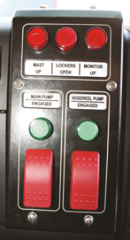
Pump engagement
There are two P.T.O.s. One drives the main pump, the other drives the
hose reel pump.
The pumps must be engaged in the following sequence:
• Main pump first, followed by the hose reel pump.
Information
• Reverse to disengage.
The hose reel pump will not work if the main pump is not engaged.
Engaging the transmission, or releasing the park brake will result in the
pumps automatically disengaging. If this happens the pumps must be
Official
re-engaged using the pump switches.
Main pump
the
To engage the main pump:
1. Stop the vehicle.
2. Apply the park brake. under
3. Shift the transmission into
Released
New Zealand Fire Service | Training
29
Section 6: Water pumps
neutral.
NOTE
4. Ensure engine is at idle.
5. Hold the main pump switch until Light On shows.
• The engine revs must be
below 900 rpm before the
6. Main pump is now ready.
PTO will engage.
• Keep the transmission in
Act
Hosereel pump
neutral at all times while
pumping.
To engage the hose reel pump:
1. Stop the vehicle.
2. Apply the parking brake.
NOTE
3. Shift the transmission into neutral.
4. Engage the main pump.
Disengaging the parking
Information
brake will disengage the
5. Hold the hose reel pump switch until the light comes on.
pump.
Pump disengagement
Main pump
Official
To disengage the main pump:
the
1. Ensure the engine is at idle.
2. Hold main pump switch until Light Off shows.
3. The main pump is now disengaged.
under
Hosereel pump
To disengage the hosereel pump:
1. Ensure the engine is at idle.
2. Hold hosereel pump switch until Light Off shows.
Released
3. The hosereel pump is now disengaged.
May 2016 | Version 7
30
Type 3 MAN T3 001- Reference Guide
Hosereels
Two Fraser Fire and Rescue hose reels are mounted on top of the
pump module. Each is fitted with 92 metres of Boston booster hose
and TFT ULTIMATIC 125, 500 kPa model BL-BGH branches, and each
hose reel is fitted with power and manual rewind systems. Circuit
Breakers are fitted to the nearside pump panel. A water shutoff valve
is positioned on the main pump panel.
Act
A friction brake is fitted to each hose reel. In the event of a power
failure, the hose can be rewound manually. To rewind the hose, insert
the supplied handle through the front of the hose reel bollard onto the
bevel gear shaft. Then push to engage the manual rewind gear with
the beveled gear on the drum.
Information
Official
the
under
Released
New Zealand Fire Service | Training
31
Section 7: Foam system
Foam Pro system
The foam system is a Foam Pro 2002 direct injection with a 53 litre
plastic tank and on-board foam refill pump.
Foam is available from both the nearside delivery outlets, both hose
reels, and the deck monitor.
The waterway is configured to deliver water only, from both offside
Act
delivery outlets.
The Foam Pro system is an electrically driven, flow-based
proportioning system that measures water flow and injects a
proportional amount of foam concentrate into the discharge side of the
pumps.
The foam system is designed for Class A foam only.
The foam proportioning and multi-flow gauges are mounted to the right
of the Foam Injector Selection switch.
Information
Foam tank
The foam tank is plastic and has a capacity of 53 litres.
The tank is located at the bottom of the offside pump panel. For
Official
manual filling of the tank, slide it out of the locker and remove the tank
lid.
the
Refilling
There is a self-priming, flexible impeller pump with a flow rate of
approximately 20 l/min, mounted behind the nearside pump panel.
This is used to transfer foam concentrate to the foam tank.
under
Foam is taken up through a pick-up tube connected at the nearside
pump panel when required.
A sensor is fitted to the top of the tank to stop the foam concentrate
pump when the level has reached a maximum.
System priming
Released
Upon receiving your new Type 3 appliance, the foam concentrate
system will need to be charged. To do this:
1. Fill the foam tank with Class A foam.
2. Turn the foam system on by pressing the red FOAM button and set
it to normal pressure.
3. Set the foam percentage to 10% by pressing the SELECT button
until the indicator is beneath “ % ”, then use the UP arrow to
increase the rate to 10%.
May 2016 | Version 7
32
Type 3 MAN T3 001- Reference Guide
4. Open a foam capable low-pressure delivery outlet and run the main
pump up to approx 150 L/min until foam is present.
5. Switch the foam system to high pressure and run a hosereel
at something close to its normal maximum output until foam is
present.
6. Close down and flush the water pump waterway as usual.
Act
7. Set the foam pump proportioner back to the normal operating
percentage. (Note: the lower the main water pump pressure the
faster the prime. Therefore do not fit a nozzle to the delivery outlet
being used).
Contents level
The foam concentrate contents gauge is mounted on the left side of
the pump panel next to the Foam Injector Selection switch.
Information
When the foam level drops to 1/8, the LED lights on the contents
gauge will begin to flash to alert the pump operator.
Foam Pro operation
High or normal pressure
Official For detailed instruction on
The Foam Pro system will inject foam into either the hosereel pump, or
the operation of the Foam
the main pump, but not both at once.
the
Pro system, refer to the
Foam Pro and Darley Pump
Making the selection between high or low pressure tells the foam
Operation manuals.
proportioning system which flow meter to monitor and which injector
to send foam concentrate to.
under
Flow measuring
The Multi-flow system performs two functions:
1. It measures water flow. This is necessary for the proportioning
system to deliver the selected percentage of foam concentrate into
the water stream
2. Displays flow rates.
Released
New Zealand Fire Service | Training
33
Section 7: Foam system
The pump operator can select from the following display options on
the Multiflow panel:
• the combined water flow through the hose reels
• the flow through the foam capable low pressure delivery.
The flow through the low pressure deliveries is measured for the foam-
capable low pressure delivery only.
Act
Foam proportioning
The foam proportioning controls include the following:
NOTE
• a button to start and stop the injection of foam concentrate (change
from delivering plain water to delivering foam solution)
Always ensure the monitor
• selection of what is displayed
is down before driving the
appliance.
Information
• adjustment of the percentage of foam concentrate injected into the
water stream.
Display options
The foam proportioner display can show:
Official
• the flow rate through the selected (high or low pressure) outlets
• the total volume of water pumped
the
• the percentage of foam concentrate being injected
• the total volume of foam concentrate that has been used.
NOTE
Remember to reset the total water and total foam displays to zero
under
before pumping. The displays are reset by pressing the and
buttons on the foam proportioner at the same time when the
appropriate reading is displayed.
After every use, ensure the
pump is flushed until no
foam residue is visible.
Getting to work with foam
Delivering foam
Released
To deliver foam solution:
NOTE
1. Start delivering water as usual.
The maximum working
2. Set the injection selector to either high or low (normal) pressure
pressure the foam system
discharge as required.
can inject foam is at 2700
kPa.
3. Check and adjust the foam percentage as required.
May 2016 | Version 7
34
Type 3 MAN T3 001- Reference Guide
4. Start the injection of foam concentrate by pressing the on/off button
on the foam proportioner control panel.
5. Monitor the contents level of the foam tank.
High / Low flow warning
Act
If the foam concentrate pump cannot supply the correct proportion of
foam it will display a warning on the foam control display.
“Lo.Flo” means there is so little water flowing that the foam system
cannot accurately supply such a small quantity of foam concentrate.
“Hi.Flo” means that there is so much water flowing that the foam pump
cannot supply enough foam concentrate to maintain the selected
concentration.
Refilling the foam concentrate tank Information
The foam tank is filled via an on-board foam refill pump as follows:
1. Connect the foam pickup tube (supplied) to the Dry Break fitting on
NOTE
the pump panel.
2. Place the other end into the foam container.
The refill pump will
Official automatically switch off
3. Press the foam pick-up pump button in until the foam starts to flow.
when either the foam tank
Hold button in to continue pump operation until foam tank is full.
is full, or the foam transfer
(Foam tank capacity = 53 litres, foam is normally carried in 20 litre
pump is dry for more than 30
the
drums).
seconds.
4. Remove the foam pickup tube.
5. Flush the pick-up and flush away any foam spilt during refilling.
under
Released
New Zealand Fire Service | Training

35
Section 8: Equipment
Crossfire monitors and Safe-Tak 125
portable base
The monitor unit mounted in the pump frame, is a TFT 18” Extend-a-
gun with a crossfire monitor, and is fitted with a Master Stream 150-
1250 nozzle. Operation of the monitor is from the body roof platform
position. The waterway open/close switch is mounted on the monitor
support tube. It will not operate until the monitor is fully extended.
Act
There is a warning light in the cab, which comes on when the monitor
is extended.
The monitor can be ground mounted, by using the Safe-Tak 1250
portable base. To ground mount:
1. Position the monitor over the base.
2. Slide it onto the portable base until the pawls engage.
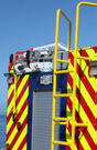
Ladders
Information
The appliance is fitted with three ladders:
• a 10.5 m rescue ladder (a 464 Rescue Ladder can be fitted)
• two access ladders.
Official
Rescue ladder is mounted on a fixed beam gantry on the top deck of
the appliance. Two access ladders are stowed in the rear locker.
To remove the rescue ladder, lift the manual release arm only when the
the
crew is positioned at the foot of the ladder. The ladder will slide back
due to gravity.
When housing the rescue ladder, ensure the head of the ladder is kept
up off the gantry, and the weight of the ladder is taken by the rollers at
the base of the gantry. Once the ladder gets beyond the tipping point
under
and the head naturally settles on the centre guide on the gantry, finish
housing the ladder.
Once housed, position the locking fork on the 2nd last ladder rounds.
Secure the manual release arm.
NOTE
The suspension may be lowered to assist removing and housing the
ladder.
The ladder must be held
before releasing, as it will
Released
slide back or forward due to
gravity.
Ladder locking pin and
manual release arm
May 2016 | Version 7
36
Section 9: Lighting
Switches
The following lights are switched on at the pump panel:
• scene lights
• pump panel light
• mast light.
Act
Note the work light master switch, located on the control head in the
cab, must be switched on.
Body roof lights are switched on and off from the work light master
switch.
Locker lights
All locker lights will come on when a locker door is opened, provided
the vehicle park lights are on.
Information
Letterbox lighting
Letter box lights are located on the roof beside the front beacons.
They are switched on from the control head in the cab.
Official
the
under
Released
New Zealand Fire Service | Training
37
Notes
Act
Information
Official
the
under
Released
May 2016 | Version 7
Act
Information
Official
the
under
Released
Document Outline