Act
May 2015
Information
Official
the
under
Released
link to page 3 link to page 3 link to page 4 link to page 4 link to page 5 link to page 5 link to page 5 link to page 6 link to page 7 link to page 7 link to page 7 link to page 8 link to page 9 link to page 9 link to page 10 link to page 10 link to page 12
 Scope
Scope
This guidance document can be used to ensure that New Zealand Fire Service (NZFS) fire
appliances can adequately access sites, buildings and structures in the event of an emergency.
The document specifically details the requirements for fire
appliance access, including general
access to sites or premises, and access around buildings or structures within a site
(allotment).
The users of this guideline should be aware that this document is an informative guideline,
and does not replace any statutory requirements.
Act
Contents
Context ........................................................................................................................................................................... 3
Definitions ..................................................................................................................................................................... 3
NZFS appliances .......................................................................................................................................................... 4
Types of NZFS fire appliances ...................................................................................................................... 4
Information
Appliance type coverage ................................................................................................................................ 5
Access requirements ................................................................................................................................................. 5
Carriageway widths ......................................................................................................................................... 5
Turning areas ..................................................................................................................................................... 6
Official
Ensuring clear access ...................................................................................................................................... 7
Kerb dimensions ............................................................................................................................................... 7
the
Building and structure clearance height ................................................................................................. 7
Gradients (e.g. access ramps) ...................................................................................................................... 8
Appliance weights (loads) ...................................................................................................................................... 9
Static loads of appliances............................................................................................................................... 9
under
Dynamic loads (on aerial appliances) ..................................................................................................... 10
Vehicle hardstand requirements .............................................................................................................. 10
References ................................................................................................................................................................... 12
Released
New Zealand Fire Service
Emergency vehicle access guidelines
2
 Context
During an emergency, the NZFS is most efficient and effective when there is suitable provision
for rapid and unhindered response by its fire
appliances. Poor or inadequate access can result
in a delayed NZFS response, with the obvious delay to intervention having a direct impact on
the life safety of occupants and the protection of property. Due to the nature of the functions
required to be performed, NZFS fire
appliances are generally larger and heavier than those
used by other emergency services.
The guidance provided is based around compliance with New Zealand Building Code Clause
C5, which addresses access and safety for firefighting operations. More specifically, Clauses
C5.3 and C5.4 of the Building Code describe the performance requirements relating to fire Act
appliance access:
“C5.3) Buildings must be provided with access for fire service vehicles to a hard-standing from
which there is an unobstructed path to the building within 20 m of:
a) the firefighter access into the building, and
b) the inlets to automatic fire sprinkler systems or fire hydrant systems, where these are
installed.
Information
C5.4) Access for fire service vehicles in accordance with clause C5.3 must be provided to more
than 1 side of firecells greater than 5,000 m2 in floor area that are not protected by an
automatic fire sprinkler system.
Performance requirements in clauses C5.3 to C5.8 do not apply to backcountry huts, detached
dwellings, within household units in multi-unit dwellings, or to outbuildings, and ancillary
buildings.” [1, p. 33A]
Official
A second key source of information on which this guidance is based are the Acceptable
Solutions C/AS1-7, Paragraph 6.
the
The NZFS also recommends the use of the Fire Fighting Facilities Checklist (FFFC) to
document NZFS agreement on specific sites access requirements. The FFFC document can be
found on the NZFS websit
e (http://www.fire.org.nz/business-fire-safety/building-
design/Documents/Fire-Fighting-Facilities-Checklist.pdf).
under
During the design of NZFS vehicle access, where appropriate the New Zealand Transport
Agency (NZTA) guidelines should also be followed.
Definitions
The following definitions apply in this document:
Aerial appliance: A specialised emergency vehicle that has an aerial apparatus which
Released
elevates to height for suppression and/or rescue.
Allowable Bearing Pressure: The calculated pressure required to counter compression
forces exerted by dead loads (i.e. the minimum strength required to maintain stability under
a weight load).
Appliance: An emergency vehicle that provides firefighting, rescue or Hazardous Materials
(HazMat) capability.
New Zealand Fire Service
Emergency vehicle access guidelines
3

Carriageway: Any construction specifically designed to be traversed by vehicular traffic
(may or may not include a sealed top surface layer).
Stabilisers: Fitted to
aerial appliances to provide stability when the vehicle’s centre of
gravity shifts during the operation of the aerial apparatus.
Hardstand area: An area designated and designed for use by a NZFS fire
appliance and its
crew, which can withstand the laden weight and associated loads of the vehicle in use.
NZFS appliances
Act
Types of NZFS fire appliances
The NZFS fleet consists of different types of vehicles, which are designed to perform specific
functions at an emergency incident. Such vehicles are collectively known within fire service
agencies as
appliances.
The vast majority of NZFS fire
appliances comprise of a specially built body fitted on a multi
axle heavy vehicle chassis. Depending on the function of each vehicle, various levels of
firefighting, rescue or hazardous material capabilities are provided by way of equipment
Information
carried.
Some
appliances perform specialised functions in the event of an emergency. Besides the
general
appliances, the second main category of
appliance is
aerial appliances. An
aerial
appliance has a specially built telescopic and/or articulated apparatus that elevates to height
for fire suppression of large premises, or to rescue trapped occupants in multi-storey
Official
buildings.
Aerial appliances are larger and heavier than general
appliances, and may be on
either a two, three or even four axle heavy vehicle chassis.
Note: The functions of an aerial appliance require that it is able to get relatively close to the
the
building or structure that it needs to attend.
The NZFS categorises its
appliances into six Types, where Types 1 to 3 represent the general
appliances and Types 4 to 6 represent the
aerial appliances.
under
While specifications vary between different
appliances, the maximum parameters (i.e. worst
case scenario) for NZFS appliances are shown in
Table 1:
Maximum parameters
Gross vehicle mass
25 t
Maximum overall length
12.6 m
Released
Maximum overall width
2.5 m (6 m when stabilisers are deployed)
Required free height
4 m
Table 1: Maximum parameters for NZFS appliances
New Zealand Fire Service
Emergency vehicle access guidelines
4

 Appliance type coverage
All sites, buildings and structures across New Zealand (NZ) should ensure all NZFS
appliances are given adequate access in the event of an emergency.
When applicable, developers and planners must also ensure that adequate access is provided
for
aerial appliances. The location of the site must be within the coverage area of an
aerial
appliance and the buildings or structures likely to require an
aerial appliance during an
emergency.
To determine whether
aerial appliance access is necessary for a given site, contact NZFS
Operations through the local Fire Area office.
Act
Access requirements
Carriageway widths
Carriageways should be wide enough to allow
appliances to easily negotiate them, and
provide sufficient room to allow vehicle crews to work with firefighting equipment around
the vehicle. During an emergency,
appliances will park along the
carriageway in the most
Information
tactically advantageous position.
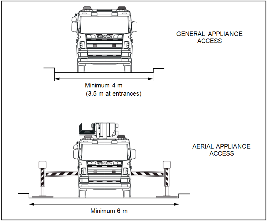
Along straight
carriageway sections, a minimum width of 4 m should be provided for general
appliance access, and a minimum width of 6 m for
aerial appliance access (see
Figure 1).
Note: Aerial appliances require additional width to fully extend their stabilisers. Where
continuous 6 m clearance cannot be provided, NZFS may consider designated hardstand areas
Official
for aerial appliance operation.
A clear passageway of no less than 3.5 m wide should be provided at site entrances, internal
the
entrances and between buildings.
under
Released
Figure 1: Minimum carriageway widths along straight sections
New Zealand Fire Service
Emergency vehicle access guidelines
5

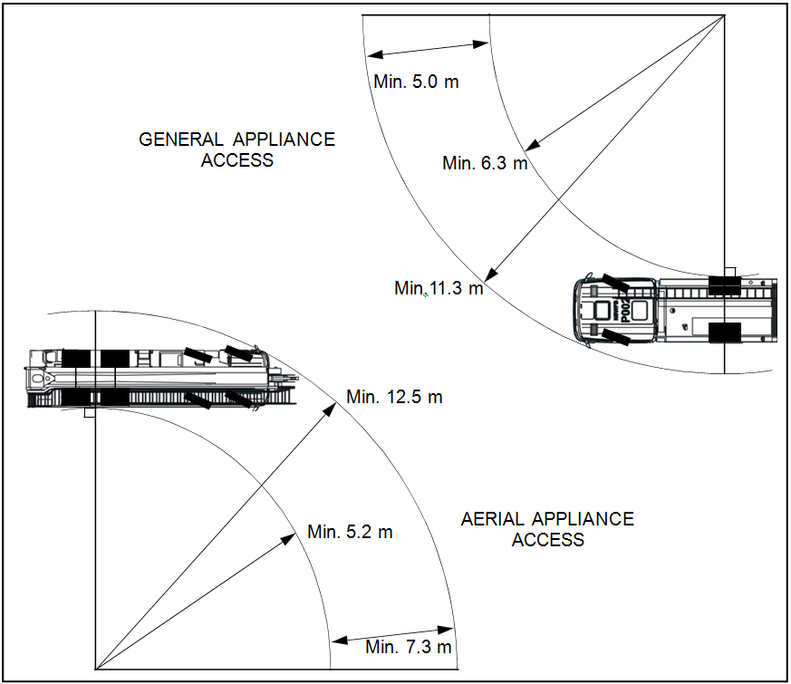
Along curved
carriageway sections, a minimum inner radius of 6.3 m and outer radius of
11.3 m should be provided for general appliance access, and a minimum inner radius of 5.2 m
and outer radius of 12.5 m for
aerial appliance access (see
Figure 2).
The distance between inner and outer turning arcs must allow for expected vehicle body
swing. The minimum distance between the inner and outer arcs should not be less than 5.0 m
for general
appliances and 7.3 m for
aerial appliances (see
Figure 2).
Act
Information
Figure 2: Minimum carriageway widths — curved sections
Note: The radius dimensions specified above are for wall to wall clearance from body overhang,
Official
and do not represent the vehicle’s wheel tracks.
Turning areas
the
Any
carriageway not leading directly to an exit (i.e. dead end) should be provided with a
turnaround area that prevents the need to perform multi-point turns.
NZFS vehicles are required, and are designed, to perform a full 360° turn within a 25 m circle
(wall to wall clearance) to meet NZTA requirements.
under
The minimum turning radius of turnaround areas should be no less than 11.3 m for general
appliances, and 12.5 m for
aerial appliances (see
Figure 2).
As per the NZTA guidelines, the Road Tracking Curves [2] as indicated in
Table 2 should be
considered.
NZFS fire appliance type
NZTA road tracking curve
Released
Type 1, 2, 3
8 m Medium Rigid Truck
Type 4, 5, 6
Large Rigid Truck
Table 2: NZFS fire appliance types in relation with the NZTA road tracking curves
New Zealand Fire Service
Emergency vehicle access guidelines
6

 Ensuring clear access
Site managers must ensure
carriageways are not fully or partially obstructed in a manner that
prevents unhindered access by
appliances, at any time. Moreover, it must be ensured that
access routes are trafficable during all weather conditions.
Note: Carriageways can be obstructed by parked vehicles, shipping containers, pallets, stored
goods, industrial bins etc.
Perimeter security points (e.g. sliding/swinging gates, boom gates, bollards, vehicle security
barriers) must not unnecessarily impede
appliances from gaining access. A minimum width of
3.5 m and height of 4 m should be provided at site entrances, internal entrances and between
Act
buildings.
Kerb dimensions
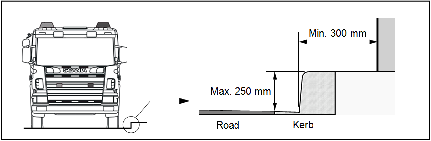
All kerbs constructed along the edges of a
carriageway should be no higher than 250 mm, and
should be free of vertical obstructions at least 300 mm back from the kerb face to allow
clearance for front and rear body overhang.
Information
Official
Figure 3: Carriageway kerb clearance dimensions
Building and structure clearance height
the
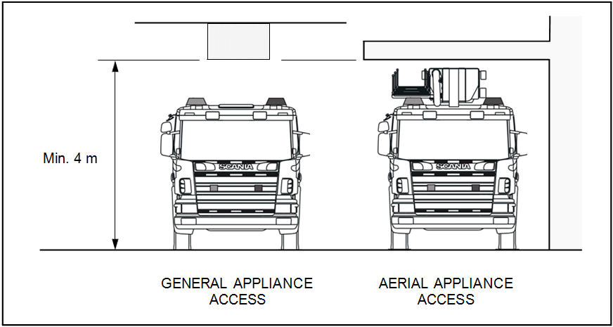
An unobstructed clearance height of 4 m should be maintained above all access ways,
including clearance from building construction, archways, gateways/doorways and
overhanging structures (e.g. ducts, pipes, sprinklers, walkways, signs, beams, trees, hanging
cables, etc.).
under
Released
Figure 4: Building and structure clearance heights
New Zealand Fire Service
Emergency vehicle access guidelines
7

 Note: Special consideration must be made where there are height restrictions in combination
with gradient changes. In some cases more than 4 m of clearance will need to be provided so the
appliance can take the gradient change.
Gradients (e.g. access ramps)
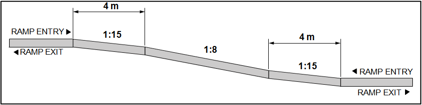
NZFS prefers a ramp gradient of 1:8 or less. The maximum negotiable ramp gradient is 1:5.
Access ramps that follow a curved or circular profile in plan view should have a maximum
gradient no greater than 1:10 (measured along the centre line).
Note: The chassis of an appliance will twist and flex when negotiating the ramp, thus a lower
Act
gradient is necessary.
Ramps should not hinder vehicle response and should provide entry/exit clearances for
appliances.
Access ramps should have a smooth transition between the main ramp gradient and
entry/exit gradients. A minimum 4.0 m long 1:15 transition grade is preferred for both ramp
approach and departure (see
Figure 5).
Information
Official
Figure 5: Maximum access ramp gradients
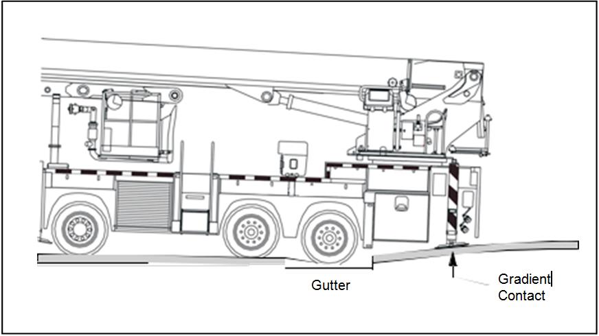
When a change of gradient includes a recessed threshold, such as a gutter (e.g. for storm
water drainage), consideration must be given to reduced approach and departure clearance
the
(see
Figure 6).
under
Released
Figure 6: Reduced gradient clearance due to gutter
Note: As wheels recede into a gutter, the effective under-body clearance height at both front and
rear overhanging sections are reduced due to the body slanting downwards. This problem is
exacerbated when the gutter depth is greater and/or when the overhang length is greater.
New Zealand Fire Service
Emergency vehicle access guidelines
8
link to page 9

Besides the general access gradients as indicated above,
hardstand gradients are limited due
to deployment of the stabilisers of
aerial appliances.
Aerial appliances can only deploy their
stabilisers and operate if the ground slope is within +/- 6°.
Appliance weights (loads)
Static loads of appliances
Carriageways must maintain structural adequacy and integrity when under load from a fire
appliance, with particular attention given to those supported, elevated or reinforced by Act
structural members (e.g. suspended floors, ramps, wharfs, aprons etc.).
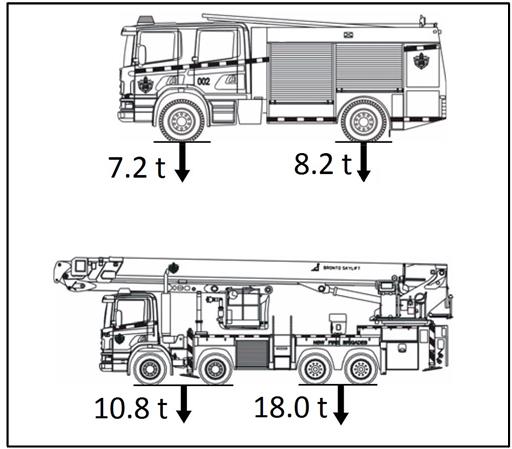
The loads of
appliances (exerted through wheels) used to determine forces acting through
load-bearing structural members are provided in
Figure 7. Wheelbase distances between the
front and back axles range from 3.7 to 5.5 m for general
appliances, and 4.4 to 5.6 m for
aerial
appliances. Distances between wheels - both longitudinal and lateral - may need
consideration when calculating point loads for wheels.
Note: Designers should be aware that the axle loads, as indicated in Figure 7, cannot be assumed
to be evenly distributed over all wheels.
Information
Official
the
under
Figure 7: Axle loads of appliances
In general, access routes should be able to withstand a laden weight of up to 25 tonnes with
an axle load of 8 tonnes, or have a load-bearing capacity of no less than the public roadway
serving the property, whichever is the lower.
Roadway pavements designed for
aerial appliances shall withstand a vehicle of multiple axles
spaced at no less than 2.5 m centres and each carrying 8.2 tonnes.
The hardness of the
carriageway surface must withstand the static pressure exerted by tyres
Released
of an appliance that is not greater than 850 kPa.
Note: The NZFS recommends that pavements for fire appliance access are designed according to
NZTA HN-HO-72 traffic loading specifications, in order to meet the load-bearing requirements.
New Zealand Fire Service
Emergency vehicle access guidelines
9

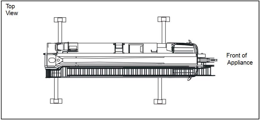 Dynamic loads (on aerial appliances)
Aerial appliances
Dynamic loads (on aerial appliances)
Aerial appliances are fitted with stabilisers that prevent the vehicle from overbalancing when
the aerial apparatus is operating.
Aerial appliances will either have two
stabilisers at the rear
only, or two front and two rear
stabilisers (see
Figure 8).
Act
Figure 8: General stabiliser arrangement on aerials
Dynamic forces exerted through the
stabilisers are caused by changing weight distribution
and other forces, such as torsion moment forces, which are created by the extension and
rotation of the aerial apparatus.
Information
Note: The ever-changing distribution of weight can cause up to 70% of the total vehicle weight
to bear on a single stabiliser.
The maximum dynamic loads and pressures exerted though a single stabiliser of the
Bronto
Skylift F44 RLX, having a fully loaded cage (500 kg) at maximum extension/outreach and
under worst case rotation angle are:
Official
Maximum stabiliser force: 200 kN
Maximum footplate pressure: 11 kg/cm² (1079 kPa)
the
Maximum bearing plate (block) pressure: 2.8 kg/cm² (274 kPa)
The maximum exerted pressure above should be considered when calculating the minimum
Allowable Bearing Pressure (ABP) for the
carriageway or hardstand area.
under
Dynamic forces exerted through the
stabilisers are caused by changing weight distribution,
and other forces such as torsion moment forces, which are created by the extension and
rotation of the aerial apparatus.
Vehicle hardstand requirements
For a fire appliance to be effective it needs to be able to park in an area as close as possible to
both the available water supply and the structure to be protected. This area is termed the
hardstand. The exact location and extent of
hardstands shall be determined in consultation
Released
with NZFS Operations.
New Zealand Fire Service
Emergency vehicle access guidelines
10

As indicated in the Building Code Clause C5.3, buildings must be provided with access for fire
service
appliances to a
hardstand area from which there is an unobstructed path to the
building within 20 m of:
a) firefighter access into the building and;
b) the inlets to automatic fire sprinkler systems or fire hydrant systems, where these are
installed.
If the floor area of a firecell is greater than 5000 m2, a
hardstand area must be provided to
more than one side of the respective firecell.
Note: The above hardstand requirements do not apply to the following classified uses (as defined
Act
in Clause A1 of the Building Code): Backcountry huts, detached dwellings, within household units
in multi-unit dwellings, outbuildings, ancillary buildings.
Designers should also refer to Paragraph 6 of the Applicable Acceptable Solution C/AS1-7 for
the appropriate hardstand requirements. Be aware that special care should be taken in case
of Acceptable Solution Risk Groups SH (C/AS1) and SI (C/AS3). A description of the different
possible Risk Groups can be found in Table 1.1 of each of the Acceptable Solutions C/AS1-7.
For example, in the case of a sleeping risk group as per C/AS1, the
hardstand shall also be
within 75 m of any point in any unit contained in the building, unless there is a sprinkler
system installed that is compliant with NZS 4515.
Information
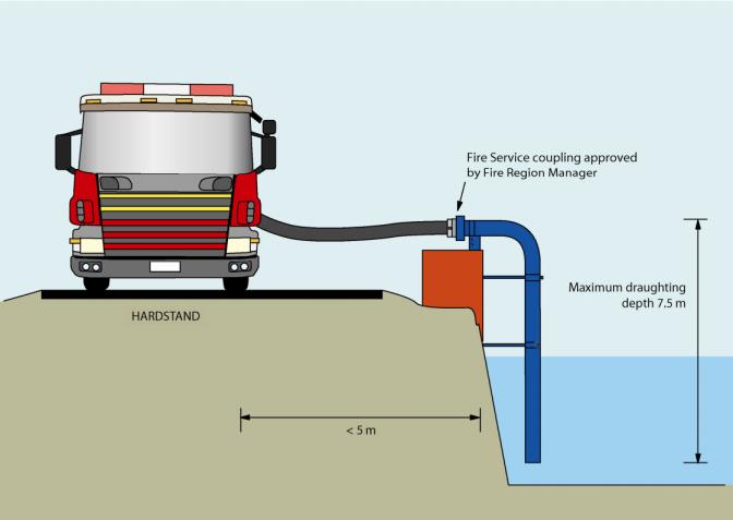
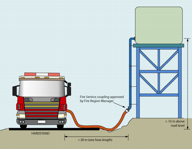
Specific guidance on the firefighting water supply near a hardstand can be found in the NZFS
Firefighting Water Supplies Code of Practice SNZ PAS 4509:2008 [3]. Depending on the water
supply circumstances, specific solutions and requirements can be found in this Code of
Practice. For example, if reticulated water supplies are unavailable or insufficient, alternative
firefighting water sources might be required near the
hardstand (see Figure 9). In order to
Official
determine the exact water supply requirements (e.g. type water supply, type connection, etc.),
contact NZFS Operations through the local Fire Area office.
the
Note: Fire districts may have a range of water supply systems such as a fully reticulated water
supply system (in an urban water supply area), a rural water supply system that feeds a supply
tank (in a rural water supply area), or a stand-alone tank supply using rain water or a local well
or bore for maintaining its contents.
under
Released
Figure 9: Examples of Suction (left) and Flooded (right) water supply sources near the hardstand
New Zealand Fire Service
Emergency vehicle access guidelines
11
 References
[1] Ministry of Business Innovation and Employment,
New Zealand Building Code Handbook, 2013.
[2] Land Transport New Zealand,
New Zealand on-road tracking curves for heavy vehicles, 2007.
[3]
New Zealand Fire Service Firefighting Water Supplies Code of Practice SNZ PAS 4509, Standards
New Zealand, 2008.
Act
Information
Official
the
under
Released
New Zealand Fire Service
Emergency vehicle access guidelines
12