EEEN 201 Mechatronic Design and Prototyping Test 1
31 August 2021
Name: ………………………………………………………………………
Student Number:……………………………………………………….
Instructions – please read
Attempt all questions
Total = 60 marks
The test will be available on the Wiki (NZ time) on Tuesday 31 August at 11 am. You have
two hours to complete the test and submit again. A few people have been allocated extra
time and that will be into account. You will then have until 1 pm (or later for extra time to
submit on the Wiki).
Type or neatly write your answers in the spaces provided. You can also electronically draw
your sketches on the document or else draw in another package and then import into this
document. Show the details of your workings where appropriate – do not just show final
answer.
The test should be completed individually, that is you may not consult with anyone to
obtain answers, but is “open book” – you may consult your class notes/videos or even the
internet. The websit
e https://www.engineeringtoolbox.com/ is a good source for any material
constants that you may need.
It is advised that you spend no more than 1.5 hours on the test and use the remaining 30
minutes to format and submit your document.
Save your document with a filename EEEN201_Test1_2021_”your surname”-“your initial”
and ensure that you submit this in the Wiki submission system no later the submission time.
Please submit as a pdf document.
Email me if you have any specific queries during the test or if any difficulty submitting.
 EEEN201 Test 1
Total Marks = 60
Q1.
[12]
EEEN201 Test 1
Total Marks = 60
Q1.
[12]
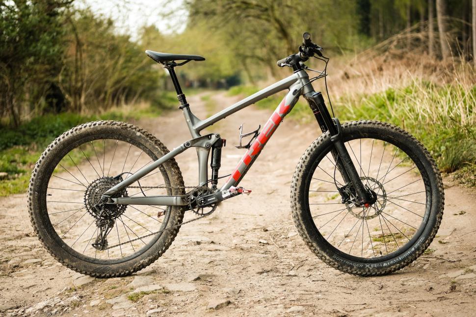
Study the objects in the two figures below and list three different materials that were likely
used in the manufacture of different parts in each object. Also state the most likely
requirements that lead to the choice of this material:
Mountain bike
Part
Likely material of
Requirements for this choice
choice
Syringe
Part
Likely material of
Requirements for this choice
choice
 Q2.
[5]
Q2.
[5]
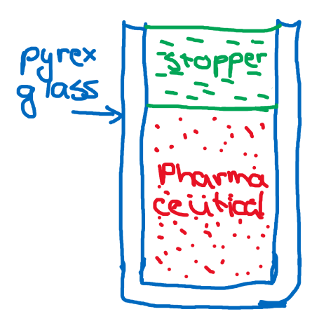
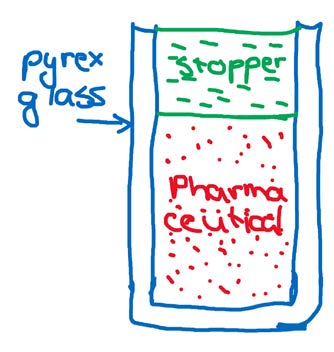
You need to design a stopper to seal a glass tube
during the heat treatment process of a
pharmaceutical product. It is stated that this stopper
must be electrically non-conductive and must be
able to form a good seal with the glass. It should also
be chemically inert and not react with the
pharmaceutical material in the tube. The
temperature during the process can be between
room temperature and 150 oC.
(a) Suggest a potential material for the manufacture of the stopper and discuss how the
properties of this material would meet the requirements.
(3)
(b) What other factor(s) should also be taken into account in the material selection and
design of these stoppers ?
(2)
 Q3.
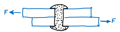
Q3. Identify type of stresses in each of the objects below.
[7]
Object
Description
Stress(es) Present
(a)
Two plates secured
by a rivet with each
plate experiencing a
force but in
opposite directions
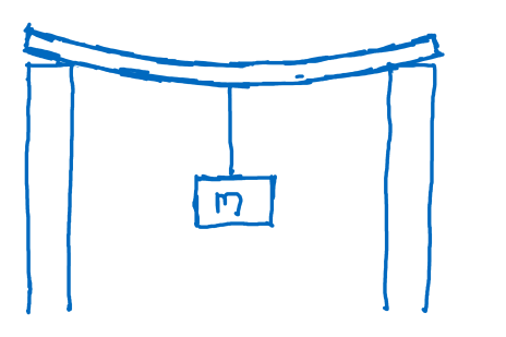
(b)
A beam rests on
two pillars and have
a rope with a mass
M is attached to the
beam.
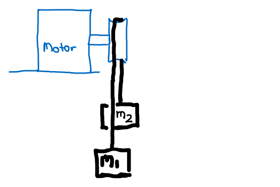
(c)
An electric motor is
driving a pulley that
has a cable over it
with two masses
M1 and M2
suspended from the
cable
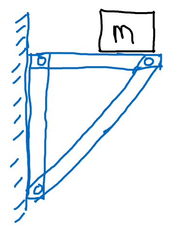
(d)
A shelf with a mass
M resting on it.
Identify the stress
in the diagonal
member.
 Q4.
[9]
Q4.
[9]
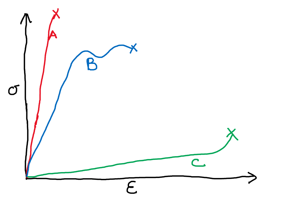
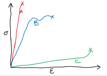
Consider the stress-strain curve below which describes the mechanical behaviour of
materials A,B and C. The point X at the end of each curve indicates the failure point of the
materials. For each of the materials discuss the properties that can be inferred from the
shape of the stress -strain curve. Also indicate what type of material each curve is most
likely to represent.
Material A
Material B
Material C
Q5.
[9]
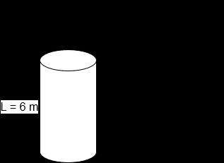
You hear that the city council is planning to erect a statue of a famous resident on a pillar in
the city square and decide to use your knowledge of mechanical properties of materials to
check their calculations. It is estimated that the statue will weigh 1000kg and they plan is to
put the it on a concrete pillar (no rebar reinforcement) with a height of 6 meters and a
diameter of 1 m.
It is given that the elastic modulus of concrete Econcrete = 17 GPa and the density of concrete
ρconcrete = 2400 kg.m-3. The ultimate compressive strength of cured concrete is approximately
50 MPa.
(a) Calculate the stress in the column and sketch a graph of stress vs height in the column.
(4)
(b) What is the most likely failure mode of the concrete in this structure ? Now make a
decision if there is a likely chance of failure.
(3)
(c) What other modes of failure of the structure should be considered ?
(2)
Q6.
[10]
In a lifting operation a piece a machinery with a mass of 500 kg is attached to the end of a
steel cable with diameter of 10 mm and a total length of 6 m. The elastic modulus of steel is
200 GPa.
(a) Model the cable as a solid steel rod and calculate the stress in the cable when you have
lifted the machinery to a height of 2 m.
(3)
(b) Also calculate the strain in the cable at this point and use that to calculate the length of
the cable at this stress point.
(2)
(c) Will the actual stress in the cable be smaller or larger than the value calculated in (a) ?
Discuss your answer and estimate the actual stress in the cable.
(4)
Q7.
[10]
Write short notes on
one of the following industrial fabrication processes:
Injection moulding of plastic parts such as Lego blocks
OR
The drawing process used in the manufacturing of aluminium cans.
In each case briefly describes the process by using drawings where appropriate and explain
how the material characteristics of the raw material lends itself to this fabrication process.
Explain why this process is not suitable for prototyping parts.
EEEN 201 Mechatronic Design and Prototyping Test 2
5/10/2021
Name: ………………………………………………………………………
Student Number:……………………………………………………….
Instructions – please read
Attempt all questions
Total = 65 marks
The test will be available on the Wiki (NZ time) on Tuesday 5 October 11 am. You have two
hours to complete and submit the test. A few people have been allocated extra time and
that will be taken into account. You will then have until 1 pm (or later for extra time to
submit on the Wiki).
Type or neatly write your answers in the spaces provided. You can also electronically draw
your sketches on the document or else draw in another package and then import into this
document. Show the details of your workings where appropriate – do not just show final
answer.
The test should be completed individually, that is you may not consult with anyone to
obtain answers, but is “open book” – you may consult your class notes/videos or even the
internet. The website
https://www.engineeringtoolbox.com/ is a good source for any
material constants that you may need.
It is advised that you spend no more than 1.5 hours on the test and use the remaining 30
minutes to format and submit your document. Save your document with a filename ”your
surname”-“your initial_EEEN201_Test2” and ensure that you submit this in the Wiki
submission system no later the submission time. Please submit as a pdf document. Email me
if you have any specific queries during the test or if any difficulty submitting.
You will also be able to sit the test in person at 11 am in MY102 on the day of the test.
Question
Points
Obtained
1
15
2
20
3
15
4
15
Total
65
Q1. Mechanical Properties calculation
[15]
Four cylindrical rods, made from a plastic material are used as the “feet” of a container. This
container can have a mass of up to 500 kg when fully laden. Each of the feet is 50 mm in length and
1 cm in diameter.
For the plastic it is given that:
Elastic modulus = 2.2 GPa
Compressive yield stress = 65 MPa
Poisson’s ratio = 0.36
(a) Calculate the maximum mass that the container can have without exceeding the compressive
stress of the plastic.
(4)
(b) Calculate the stress and resultant strain on each of these feet when the container has a mass of
500 kg.
(4)
(c) What would be the actual dimensions of one of these feet (length and diameter) when the
container has a mass of 500 kg ?
(4)
(d) You leave the container loaded to 500 kg for a period of several months. At the end of this
period you take off the feet and examine them and come to the discovery that the feet has actually
permanently deformed, as both the length and diameter of the feet are now different from the
initial dimensions. According to your calculations you have never exceeded the elastic limit of the
material. Can you explain this phenomenon ?
(3)
 Q2. Design of a compliant mechanism
[20]
Q2. Design of a compliant mechanism
[20]
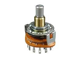
You must design a rotary switch operating
similar to the one in the picture on the right.
This switch must rotate 360o around a shaft,
and must have four engage positions during a
rotation where the shaft will lock and the
rotation stop. In order to disengage from one of
these locked positions, an increased torque
must be applied to the shaft, after which the
shaft should rotate relatively freely until the
next lock position is encountered.
You should do this design utilising the elastic properties of materials, i.e. you must design a
compliant mechanism to achieve your objective. The following design specifications are given:
• It must be a four-position mechanical rotary switch with lock position every 90o. It should be
able to rotate with equal ease in a clockwise or in an anti-clockwise direction.
• An operator should be able to lock and unlock this by hand.
• The device should fit into a volume of 50 x 50 x 50 mm.
• You can use laser cutting (acrylic) or 3D printing or a combination of the two to produce your
device.
• The shat of your device can be an off-the-shelve metal part, so you do not have to design the
shaft.
Important: You do not have to include any of the electrical contacts or connections shown in the
example picture – your design should only concentrate on the mechanical movement.
(a) Sketch (by hand) your design for this device and explain how the device will operate. You should
include approximate dimensions in your drawings and the drawings should be able to serve as an
initial design.
(10)
(b) Explain what elements in your design will determine the torque required to unlock the shaft from
a locked position.
(5)
(c) One of the design specifications is that you should be able to operate the switch by hand. It
would then be good to know what the typical torque is that can be generated by the hand
movement of a human operator. Describe some tests/experiments that you can perform to get an
estimate of this torque.
(5)
 Q3. Motors
[15]
Q3. Motors
[15]
Discuss the differences between stepper motors and servos with regards to the following aspects:
(a) The basic construction and operation of each of these types of motors.
(8)
(b) The advantages and disadvantages of these types of motors
(3)
(b) Explain in what type of application you will use each of these types of motors.
(4)
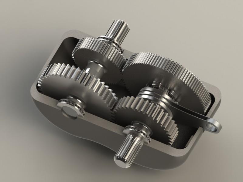
Q4. Power Transmission
[15]
A small two speed gearbox is shown in the diagram. It can be used so that
either the upper pair of
gears
or the lower pair of gears are engaged at any time.
(a) Estimate an approximate gear ratio for each of the gear pairs, making sure that you explain how
you arrived at your answer.
(5)
(b) It can be seen that the two sets of gears have a different gear pitch (or module). Explain why
using different pitches would be useful in this application.
(5)
(c) The gearbox shown has an input and an output shaft, but it is not immediately obvious which is
which. Using your answer to part (b), or otherwise, would you connect your motor (the input) to the
upper-left or the bottom-right shaft?
(5)
EEEN201 Test T2 2022
Question 1: Multichoice
[10 Marks]
i.
You’re designing a cooling system for an aeroplane’s landing gear. It contains a heatsink that
cannot be mounted to the aeroplane’s airframe. The cooling mechanism between the heatsink
and air at altitude will…
a. Be approximately the same as at ground level
b. Be approximately 70% Radiation and 30% Convection
c. Be approximately 30% Radiation and 70% Convection
d. Be approximately 30% Radiation and 70% Conduction
(2)
ii.
Adding a fan to a heatsink changes the cooling system from natural convection/radiation to forced
convection. How will this modify the magnitude of the convection heat transfer co-efficient?
a. Multiplied by 0.1
b. Multiplied by 0
c. Multiplied by 1
d. Multiplied by 10
(2)
iii.
The diagram below illustrates typical engineering stress strain relations for three materials. For
material A, what type of material is this likely to be?
a. ABS plastic
b. TPU plastic
c. Metal
d. Ceramic
(2)
You’re asked to calculate the stress and strain on a granite support. The granite has a cross sectional
area of 0.5 m2, and is 6 m long. The granite has a tension force of 25 kN applied. Granite has a Young’s
modulus of 4.5 x 10⁷ kPa.
iv.
What is the engineering strain on the granite support?
a. 50 kPa
b. 50
c. 0.001 kPa
d. 0.001
(2)
v.
What is the engineering stress on the granite support?
a. 50 kPa
b. 50
c. 0.001 kPa
d. 0.001
(2)
Question 2: Stress and Strain
[10 Marks]
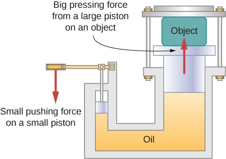
In a hydraulic press, a 250 l volume of oil is subjected to a 16 kPa pressure increase. If the oil has a
bulk modulus B of 5000 kPa
a) Find the bulk strain and the absolute decrease in the volume of oil when the press is
operating.
(4)
The compressibility of water is approximately 2.3 times that of the oil.
b) Using this approximation, calculate the new bulk strain and volume change using water
instead of the oil.
(4)
c) Why do the concepts of Young’s modulus and shear modulus not apply to fluids?
(2)
Question 3: Thermal Analysis
[10 Marks]
You’ve sent a trial PCB for testing the thermal characteristics of an LM7805. The thermal
characteristics for various LM7805 packages are as follows;
Package
Maximum 𝑇𝐽 (℃)
𝑅𝜃𝐽𝐶 (°C 𝑊
⁄ )
𝑅𝜃𝐽𝐴(Effective) (°C 𝑊
⁄ )
TO-3
150
4
39
TO-220
150
4
54
SOT-223
150
4
174
The device is designed to operate with an ambient temperature of 60 °C with a 2 W thermal load.
a) Calculate the junction temperatures of the TO-3, TO-220, and SOT-223 packages. Which
packages have junction temperatures under the maximum junction temperature?
(6)
b) You apply a heatsink, with a 𝑅𝜃𝐶𝐴 = 10 (°C 𝑊
⁄ ), calculate the new junction temperatures of
the TO-3, TO-220, and SOT-223 packages. Which packages have junction temperatures under
the maximum junction temperature?
(4)
Question 4: Design for manufacture
[10 Marks]
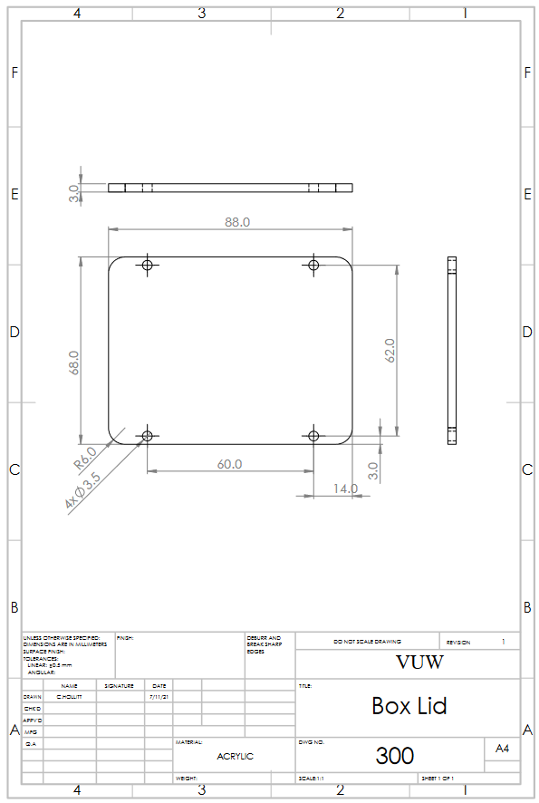
You’ve been asked to review a case design consisting of a Box Base, Box Lid, and Box Body (drawings
attached). The case houses a small LM7805 Voltage regulator PCB, and the PCB requires four panel-
mounted connections through the side of the case to the outside world. The PCB attaches to the
bottom of the case, and is mounted to the underside of the case with standoff screws. Look at the
mechanical drawings of the case. Identify a problem with the case design and suggest how the design
could be improved to eliminate the problem.

EEEN 201 Mechatronic Design and Prototyping Test
19/09/2023
Name: ………………………………………………………………………
Student Number:……………………………………………………….
Instructions – please read
Time = 100 minutes
Total = 65 marks
Attempt al questions You can bring one A4 sized sheet with your own notes on both sides with you into the
test.
Write and/or sketch your answers in the test book provided. Show the details of your
workings where appropriate – do not just show final answer.
Use the times in table below as a guide to the time you should spend on each question.
Test starts on page 3.
Question
Points
Approx. time Obtained
to answer
1. Material
12
15 mins
properties.
2. Material
12
15 mins
selection
3. Design of
16
25 mins
mechanisms
4. Motors and
15
20 mins
mechanisms
5. Electronic and
12
15 mins
mechanical design
Maximum marks
65
90 mins + 10
mins review
1
2
Q1. Mechanical Properties of materials
[12]
Four cylindrical rods, made from a plastic material are used as the “feet” of a container.
Each of the feet is 50 mm in length and 1 cm in diameter. When the container is fully filled,
it will have a total mass of 500 kg (container + fill material).
For the plastic it is given that:
Elastic modulus = 2.2 GPa
Compressive yield stress = 65 MPa
Poisson’s ratio = 0.36
(a) Calculate the stress and resultant strain on each of these feet when the container has a
mass of 500 kg. Wil it exceed the compressive stress of the plastic ?
(5)
(c) What would be the actual dimensions of one of these feet (length and diameter) under
these load conditions ?
(4)
(d) You leave the container fully loaded for a period of several months. At the end of this
period you take off the feet and examine them and discover that the feet have actually
permanently deformed, as both the length and diameter of the feet are now different from
the initial dimensions. According to your calculations you have never exceeded the elastic
limit of the material. Can you explain this phenomenon?
(3)
3
 Q2). Material selection
[12]
Q2). Material selection
[12]
Study the image of a modern electric kettle shown below. The kettle design differs from the
“old style” traditional kettle in that you can see the level of the water and there is no plug-in
power cord.
Manufacturer’s Description
• Soft opening lid prevents
hot water splattering, and
staggers steam release.
• The large, 1.7 liter cord free
jug features high visibility
BPA free* water windows,
concealed element and a
removable scale filter.
• The Soft Top™ Pure will
automatically shut itself off
when it reaches its boiling
point.
(a) Make a list of the different types of materials that have been used in the production of
this product. Also think of the kettle parts that are not visible in the image. Explain why you
think each of these materials has been chosen and what properties would be required from
the material.
[8]
(b) Discuss some potential failure modes for this kettle during long term during long term
use. Motivate your answers.
[4]
4
 Q3. Design of a compliant mechanism
[16]
Q3. Design of a compliant mechanism
[16]
You must design a rotary switch operating
similar to the one in the picture on the
right. The body of the switch stays fixed
and a shaft must rotate through 360o.
During each rotation it must encounter four
engage positions where the shaft wil lock
and the rotation stop. To disengage from
one of these locked positions, an increased
torque must be applied to the shaft, after
which the shaft should rotate relatively
freely until the next lock position is
encountered.
You should do this design utilising the elastic properties of materials, i.e. you must design a
compliant mechanism to achieve your objective. The following design specifications are
given:
• It must be a four-position mechanical rotary switch with lock position every 90o. The
shaft should rotate with equal ease in a clockwise or in an anti-clockwise direction.
• An operator should be able to lock and unlock this by hand.
• The device should fit into a volume of 50 x 50 x 50 mm.
• You can use laser cutting (acrylic), 3D printing or a combination of the two to
produce your device.
• The shat of your device can be an off-the-shelve metal part, so you do not have to
design the shaft.
Important: You do not have to include any of the electrical contacts or connections shown
in the example picture – your design should only concentrate on the mechanical movement.
(a) Sketch your design for this device and explain how the device wil operate. You should
include approximate dimensions in your drawings and the drawings should be able to serve
as an initial design.
(10)
(b) Explain what elements in your design will determine the torque required to unlock the
shaft from a locked position.
(3)
(c) One of the design specifications is that you should be able to operate the switch by
hand. It would then be good to know what the typical torque is that can be generated by
the hand movement of a human operator. Describe a tests/experiments that you can
perform to get an estimate of this torque.
(3)
5
Q4. Motors and mechanisms
[15]
(a) Discuss the basic construction, design and control of a servo motor and compare the
advantages and disadvantages of these types of motors to a stepper motor. Also explain
what types of application wil be most suitable for each of these types of motors. (10)
(b) You must now convert the rotational motion of a servo motor to a reciprocating (back
and forth) linear motion such as driving a piston. Sketch one type of mechanism that can be
used and briefly explain how this mechanism functions.
(5)
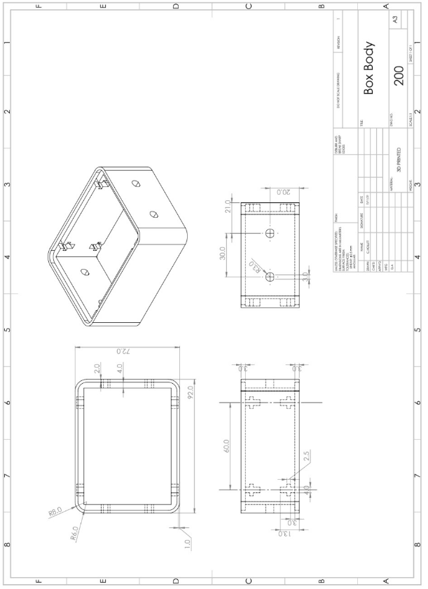
Q5. Electronic and Mechanical Design
[12]
You have been asked to review the design drawings of an enclosure for a 2-port network.
After the review, the design wil be sent to the fabrication team to be created and assembled.
Two lid components and a single base component are manufactured to create the design. A
lid component is fastened to the top and bottom of the base component to assemble the
enclosure using four M3 bolts, with M3 nuts encapsulated inside the base component. The
design has been given to you in the form of some Solidworks drawings, shown at the back of
the test. These are the drawings that the fabrication team wil receive.
Identify any issues that could potential y cause problems for the engineering team to manu-
facture or assemble the design. You must identify each issue and explain why this issue could
be a problem.
6
4
3
2
1
USE M3 BOLTS TO FASTEN TO BASE
Symmetric design about centre
F
F
98.00
E
E
3.00
3.00
D
D
16.50
C
C
3.00
B
B
UNLESS OTHERWISE SPECIFIED:
FINISH:
DEBURR AND
DIMENSIONS ARE IN MILLIMETERS
BREAK SHARP
DO NOT SCALE DRAWING
REVISION
SURFACE FINISH:
EDGES
TOLERANCES:
LINEAR:
ANGULAR:
NAME
SIGNATURE
DATE
TITLE:
DRAWN
CHK'D
APPV'D
A MFG
A
Q.A
MATERIAL:
DWG NO.
A4
TestQuestion
WEIGHT:
SCALE:1:1
SHEET 1 OF 2
4
3
2
1
4
3
2
1
R8.00
R6.00
20.00
F
15.00 F
A
A
30.50 34.50 37.00
E
E
R3.25
Recess provided
for panel mounted
2-port plugs.
SECTION A-A
D
D
t joint
1.00
4.00
11.00
20.00
40.00
3.00 3.00 2.50 4.50
91.00
2.50
C
104.00
C
t joints illustrated in SECTION A are
to encapsulate M3 Nuts inside the BASE
when LID is fastened with M3 bolts.
B
B
Symmetric design about centre
UNLESS OTHERWISE SPECIFIED:
FINISH:
DEBURR AND
DIMENSIONS ARE IN MILLIMETERS
BREAK SHARP
DO NOT SCALE DRAWING
REVISION
SURFACE FINISH:
EDGES
TOLERANCES:
LINEAR:
ANGULAR:
NAME
SIGNATURE
DATE
TITLE:
DRAWN
CHK'D
APPV'D
A MFG
A
Q.A
MATERIAL:
DWG NO.
A4
TestQuestion
WEIGHT:
SCALE:1:2
SHEET 2 OF 2
4
3
2
1
Symmetric design about centre
EEEN 201 Mechatronic Design and Prototyping Test
27/09/2024
Name:
Student Number:
Instructions
Time = 90 minutes
Total = 60 marks
Attempt al questions You can bring one A4-sized sheet with your own notes on both sides into the test.
Write and/or sketch your answers in the open space. Blank sheets are provided at the back
where you can do rough calculations and sketches.
Show the details of your workings where appropriate – do not just show final answer.
Careful y read every question before you start. Clearly state any assumptions you make
when answering a question. Where appropriate use sketches with suitable labels to
illustrate your answers.
The test starts on page 2.
Question
Marks
Obtained
1.
15
2.
10
3.
15
4.
10
5.
10
Maximum marks
60
1
 Question 1
[15]
Question 1
[15]
You are employed in the engineering design section
of a pharmaceutical development company. Your
manager has asked you to design a stopper to seal a
glass tube during the experimental heat treatment
of a new pharmaceutical product. During the
conversation, your manager stated that the stopper
should meet the fol owing requirements:
• It must form a secure fit and a good seal with the
glass.
• It should be chemically inert and not react with
the pharmaceutical material in the tube.
• It must withstand a temperature cycle between
room temperature and a higher temperature.
• An operator must be able to fit and remove this
stopper relatively easily by hand.
The glass tube has in inner diameter of 18.0 mm, an outer diameter of 20.0 mm and a
length of 100 mm.
(a) Briefly discuss the potential materials that could be used to fabricate this stopper and
explain what material properties should be considerd based on the design requirements.
(5)
2
(b) Now use the requirements from your manager to generate some initial design
specifications for this stopper. Remember that specifications should be quantifiable and
potentially easy to measure. Clearly state where you are making assumptions or when more
information would be required.
(10)
3
Question 2
[10]
Assume that the mechanical workshop has produced the first prototypes of the stopper you
designed in
Q1. You must now design a series of tests that wil measure the performance of
this part in meeting your design specification. Briefly describe the different tests and
measurements you will perform to compare the actual performance of the part to the
design specifications in Q1(a). Keep in mind that you must aim to obtain quantative data
measuring the performance of your design.
(10)
4
Question 3.
[15]
You have been asked to design a motorised microscope stage. Such a stage wil allow an
operator to place a sample under a microscope, with the sample then automatically moved
in small steps within the field of view of the microscope. At every step, an image of the
sample will then be taken by a camera system attached to the microscope. The process
should be controlled by a microcontroller-based system such as an Arduino. The system will
allow the user to set parameters such as the distance to move between taking each photo.
Assume that the stage only needs to move in one dimension.
(a) Draw a high-level block diagram showing all the sub-systems that need to be integrated
in order to successfully complete this design.
(5)
5
(b) You decide to use a stepper motor to drive the movement of the microscope stage.
Sketch
two different mechanisms that can convert the stepper motor's rotational motion
into linear motion to move the stage. For each mechanism, briefly explain how your
mechanism operates and if there are any advantages or disadvantages associated with the
mechanism in this application.
(10)
6
Question 4.
[10]
You hear that the city council is planning to erect a statue of a famous former mayor on a
pil ar in the city square and decide to use your knowledge of the mechanical properties of
materials to check their calculations. It is estimated that the statue wil weigh 1000 kg and
they plan to put the statue on a concrete pillar (no rebar reinforcement) with a height of
6 m and a diameter of 1 m.
It is given that the elastic modulus of concrete Econcrete = 17 GPa and the density of concrete
ρconcrete = 2400 kg.m-3. The ultimate compressive strength of cured concrete is approximately
50 MPa.
(a) Calculate the stress in the column and sketch a graph of stress vs height in the column.
(4)
7
(b) What is the most likely failure mode of the concrete in this structure? Now, decide if
there is a likely chance of failure.
(4)
(c) What other failure modes of the structure should be considered?
(2)
8
 Question 5
[10]
Question 5
[10]
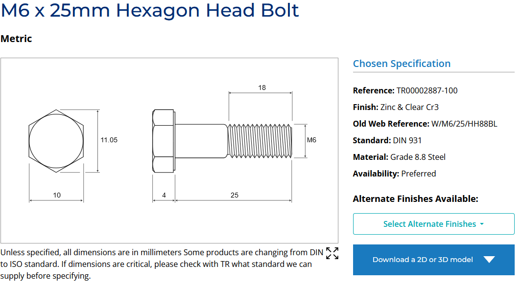
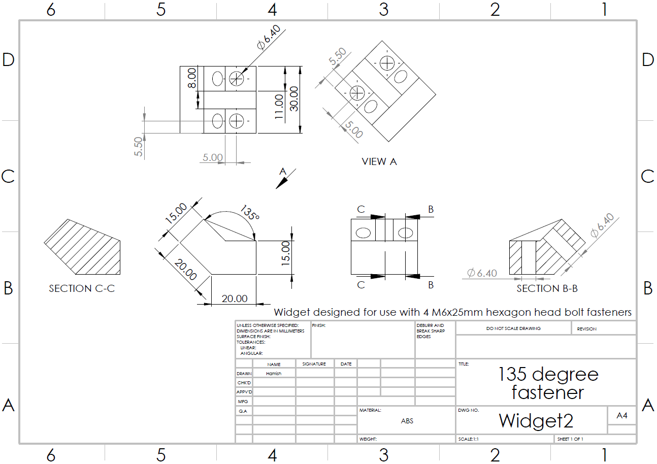
You have been asked to review the design for a widget that enables the fastening of two
objects at an angle of 135° as illustrated below. The design has been given to you in the
form of a mechanical drawing titled “135 degree fastener” shown on the test script's next
page. The widget wil be fastened to the two objects via 4 x M6 bolts. These bolts are
detailed below.
Widget
PTO for mechanical drawing
9
 PTO for questions
10
You should now:
(a) Inspect the mechanical drawings of the widget and identify a flaw in the design. Ensure
that you explain why this is a flaw and the impact of the flaw.
(4)
(b) For the flaw identified, describe modifications to the widget you would make to resolve
the flaw. Ensure you explain how the modification resolves the flaw and any caveats
associated with the modification made.
(6)
11
12
13
14
Document Outline