 Drainage
The purpose of a drainage inspection is to ensure that buildings in which sanitary fixtures and
sanitary appliances using water-borne waste disposal are installed, are provided with an
adequate plumbing and drainage system to carry foul water to appropriate outfalls; and if no
sewer is available, an adequate system for the storage, treatment, and disposal of foul water
Code clauses:
B1, B2, E1, F5, G12-13, G14
Page 30
September 2022
AC3601.17 (v.2)
Inspection requirements:
Type
Minimum requirements
Drainage
This inspection may occur at any time throughout the building process
• prior to backfil ing the drains
• all bedding material in place
• drains laid and on test
• building foundations must not be undermined
• Drainlayer must be on site for this inspection and provide a fully dimensioned
drainage plan
General information:
A drainage inspection maybe conducted at anytime throughout the development, sometimes it is done
before building works are commenced but this usually only happens if there are site constraints. The
approved plans and building consent documentation must be on site for an inspection to be approved.
No plan, no inspection
The most common problem with drainage is that it wil not be as per plan, either the system has been
changed from say G12 NZBC to AS3500 or the Drainlayer decides it is easier to change the layout due
to the nature of site. It is fair to say that most designers do not understand AS3500, which is preferred
by Drainlayer and so tend to design to G12 NZBC.
It is crucial that the Drainlayer provide an as-built at the time of the inspection in order that the layout
maybe confirmed:-
• drainage as-built plans must detail the drains as-laid and show dimensions
• drainage as-built plans must be provided at the time of the inspection
No as-built, no inspection
Always review the Drainlayer’s registration and ensure this is recorded along with his name and address
on the inspection record.
Testing of drains
Al drains must be on test at the time of the inspection and should not be back-fil ed, however partial back-
fil ing maybe acceptable in inclement weather conditions to prevent the pipes becoming displaced.
Drains maybe either smoke, water or air-tested. Where a gradient is questionable use your level to
determine the fall. Minimum falls must be maintained to prevent blockages. It is good practice to record
the gradient on the inspection record along with the pipe material and size. G13 NZBC states that drains
laid at less than 1:60 grade need to be checked with a verifiable levelling device i.e. Dumpy or laser.
Water test
A water test essentially is where you cap off the drain and fil it with water. Once fil it is just a matter of
observing it for 5 minutes to ensure that it is not leaking. If it does not maintain its level, then it fails the
test.
This test method is limited to a maximum of 1,000 metres and a maximum of 6.0m of head, the minimum
amount of head is 1.0m.
Page 31
September 2022
AC3601.17 (v.2)
Smoke test
Smoke tests are generally only conducted on commercial premises where multiple stacks are involved.
Cap off each stack (leaving the top most vents for each stack open) and fil with smoke. If smoke escapes
from any of the joints, then it fails the test. This method is not very common.
Air test
The most common way for testing a drain is where all outlets are capped and a special fitting (called an
air-test plug) with a rubber hose fitted to it, is plugged into the end of the line. The Drainlayer then
physical y blows air into the drain via the hose. After blowing air into the drain the tube is quickly placed
it into a bottle containing at least 300ml of water. Typical y, an old clear plastic bottle is used for this
purpose.
The water wil bubble up and when it stops bubbling, it has reached its pressure. If the water goes back
up the tube, then it is indicating a leak. This test should be observed for about 2 minutes.
Note that if the water continues bubbling, this could be because of the sun heating the hose.
Water is ½ a pound per foot, so wil hold ½ a pound of pressure when a successful test has been
completed.
Cross-connections
Always check that the drain is discharging to the correct outfall, sewer or stormwater. Manhole lids are
generally coloured red for sewer and blue for stormwater. The most critical element is to ensure that
cross-connection does not occur. If you are not sure that the correct drain has been identified, get the
Drainlayer to tap on the manhole lid while you are at the other end of the line and listen for the echo (it
wil travel to you).
If the drains are not on test, no approval can be given
G13 NZBC
Wherever possible PVC pipe should be used; however, in older parts of the city, clay or concrete pipes
maybe found. Al PVC pipes should be joined using solvent based primer; usually coloured pink, and the
joint maybe glued. The layout should be simple with minimal changes in direction to prevent blockages.
“NZS 7643 Code of Practice for the installation of unplasticized pvc pipe systems” covers the
requirements for jointing of pipes. Connections must be made using oblique or sweep connections
maximum with a maximum angle of 60 degrees.
Al pipes must be laid on a granular base with a maximum particle size of 20mm, this is important because
it provides support for the pipes when the trench is back-fil ed. The granular fil must be compacted
before the drains are laid. Failure to insist on appropriate bedding can see the pipe become stressed
and damaged, particularly when the ground is expansive clay, which is subject to shrinkage and
expansion. In some circumstances excavated soil maybe used, refer to Appendix D, NZS 7643 Code of
Practice for the installation of unplasticized PVC pipe systems for further information.
Pipes must be protected from damage. Pipes penetrating through concrete or masonry elements shal
be either wrapped with a flexible material, or passed through a sleeve or duct, to permit free movement
for expansion and contraction. Pipework in or under a concrete slab must be installed in a manner to
achieve a 50 year durability.
Pipes buried under ground must have protection from the loads imposed on them, to ensure adequate
protection the following clearances are required: -
Page 32
September 2022
AC3601.17 (v.2)
 Cover – G12
Location
Cover – G12
Location
600mm
Residential driveways and similar areas subjected to occasional
heavy traffic
450mm
Gardens, lawns or other areas not subjected to traffic
Cover – AS3500
Cast iron
Other
Location
300mm
500mm
Where subject to heavy vehicular traffic
300mm
450mm
Where subject to light vehicular traffic
Nil
300
Gardens, lawns or other areas not subjected to traffic
If these clearances are compromised, the drain must be protected from damage, in the following manner:
• 100mm reinforced concrete in areas subject to heavy traffic
• 75mm brick or concrete paving in areas subject to light traffic
• 50mm brick or concrete paving in other areas
The minimum diameter for a drain is 100mm although 80mm pipes can be used if the drain is receiving
discharge from a vented waste stack only. Where there is insufficient fall to a drain such as below ground
level in basement situations, a pump maybe installed. In this scenario, pumps must be fitted with a
warning device (alarm) and carry signage. The pump should be located as close to the fixture as possible
and the holding tank fitted with a vent.
Al drains must be vented to minimise the build-up of foul air. Every main drain and any branch drain
longer than 10m must be vented, the diameter of the vent being 80mm minimum.
The trench should not be left open for more than 48 hours and should not undermine the building
foundations. Whatever the depth of trench, that is the distance the drains must be away from the building,
i.e. 45 degrees, this is known as the angle of inference.
The 45-degree inference line is taken from the
bottom of the foundations, for example if
foundations are 450mm deep and the trench is
1.2m deep then the trench must be located a
minimum of 750mm away from the building.
1.2m - 450mm = 750mm
The measurement is always taken from the
underside of the footing.
Drains must be laid to allow easy access for maintenance and the clearance of blockages, with the fitting
of access, inspection points or cleaning eyes.
Drains located under buildings must be laid straight and of even gradient with a 25mm separation
between the pipe and the building foundations. The drain must also have 50 mm clearance from the top
of the pipe to the underside of the slab, and junctions beneath the building joined at an angle of not more
than 45-degrees.
Access points must be provided in the following locations:
• immediately prior to drain outfalls
• immediately inside the boundary of the property served
• at the junction of every drain with another drain except that no access point is required where the
branch drain is less than 2.0 m long and only serves a gully trap
• every change in horizontal direction of greater than 45°
• every change in gradient greater than 45°
• at intervals (on straight lines) of no less than 50 m where rodding points are used or 100 m where
access chambers, inspection chambers or inspection points are used
Page 33
September 2022
AC3601.17 (v.2)
• within 2.0 m outside the building where a drain enters or exits from under a building
Connection to public drain
When connecting to the public drain it is important to ensure that wherever possible all private drainage
is within the property boundaries and that cross-connection does not occur. However, Auckland Council
has numerous situations where private drainage is located outside the property boundary; in these
instances, the work is subject to Development Engineering approval and a maximum distance of 30
metres from the site in question.
If the drain or lateral is not located where shown on the plans, it is important that an amendment is
obtained so that Council records can be amended / updated. Where the connection is close to the
dwelling and the depth exceeds the angle of inference, protection of the drain and foundations must be
considered.
Gully traps
Al gully traps must be constructed to prevent the ingress of surface water and foreign bodies likely to
cause a blockage. Gully traps must also be located within the legal boundary of the land on which the
building is erected, and the overflow level of the gully dish must be no less than:
• 25 mm above paved surfaces, or
• 100 mm above unpaved surfaces and
• grating that wil allow surcharge
• a minimum outlet pipe diameter of 100 mm
• a water seal depth of at least 65 mm
• at least one discharge pipe discharging to the gully trap to avoid water seal evaporation or a hose
tap installed above
• waste pipes that discharge to the gully trap should be arranged to permit easy cleaning of the
gully trap
• waste pipe outlets located at least 20 mm above water seal level, and at least 20 mm below the
grating
• the top of the water seal no more than 600 mm below the top of the gully dish, and
• adequate support from bedding and backfil ing with:
o concrete no less than 75 mm thick surrounding the entire gully dish and which is separated
from the building foundation, where the gully trap is likely to be damaged, or
o compacted bedding material
o a minimum of 600 mm clear access space above the gully dish for cleaning purposes
Every building used for housing must have at least one gully trap, positioned so that the top of the gully
dish is no less than 150 mm below the overflow level of the lowest sanitary fixture served by the drainage
system. This must be located in a visible position and is installed so that surcharge cannot enter into or
under the building.
The most common problem with gully traps is that when installed they are too low, when conducting a
drainage inspection discuss and determine finished ground levels and have the Drainlayer install a riser
if the level is too low. It is much easier for this to be done now, rather than be picked up later at the final
inspection.
Another problem occurs when pipes are fitted in a manner that prevents the grate from becoming
dislodged in the event of a blockage. If pipes penetrate the back of the dish they must be sealed to
prevent water getting in behind the trap. Silicone or concrete is not adequate; refer to G13 for approved
details. If the gully trap is located more than 3.5m away from the fitting (fixture) it serves, an air-
admittance valve must be installed. Within the fixture discharge pipe but not more than 3.5m from the
crown of the fixture trap.
Page 34
September 2022
AC3601.17 (v.2)
AS3500
Drains must be laid to an even grade, straight and have no lipped joints or internal projections. They
must be continually supported, be protected against damage and watertight. Connections to the public
line may not be less than DN100. The minimum size of a main drain is 100mm and a branch drain is
65mm.provided that no soil fixtures are connected to it.
The minimum gradient is:
• 1:60 for 80 -100mm diameter
• 1:40 for 65mm diameter
The main drain must be provided with an inspection shaft in or near the point of connection to the sewer
that is not subject to flooding. Inspection shafts must terminate at or near the ground and be fitted with
an air-tight removable cap suitably sealed. The shaft must be protected from damage in an accessible
position.
Venting
Vents are required in the following situations: -
• at each end of any drain incorporating a boundary trap, provided that the downstream vent is
located within 10m of the boundary trap riser and no other fixture is connected between the trap
and vent
• upstream end of any drain not incorporating a boundary trap
• upstream of any branch drain to which a fixture trap or floor waste gul y is connected, if the
distance to the weir exceeds 10m
• upstream of any branch drain to which 3 or more WC’s are installed
• along the line of a vented drain where 10 or more WCs are installed
Unvented branch drains
The maximum length of an unvented branch drain is: -
• 2.0m for WC’s with DN80 discharge pipes
• 2.5m for all other fixtures
Unvented drains discharging to gullies may receive discharge from waste fixtures provided that the
combined length of the unvented drain and fixture discharge pipe does not exceed 10m.
Gullies
Gullies are used to provide relief in the event of surcharge or provide disconnection between waste
discharges and the remainder of the sewage installation.
Gullies must be: -
• self cleansing
• supported on a 100mm bed of concrete
• have the top of the gul y protected from damage by means of a concrete surround (minimum width
of 100mm around and 100mm deep below ground)
• be protected with haunching – haunching must extend 25mm above paved surfaces or 100mm
above unpaved surfaces
• have a grating to relieve surcharge
• have a permanently maintained water-seal provided by
o discharge from a waste fixture or floor waste gully
o water from a tap located over the gully
o discharge from a waste stack no > 5 floors in height (discharging below the grate but above
the water seal)
Note that WCs and surface or roof water must not discharge into a gully.
Page 35
September 2022
AC3601.17 (v.2)
Disconnector gullies
Disconnector gullies maybe located inside a building provided that the gully riser extends to floor level
and is sealed with a removable lid. It must also be vented with a DN50 vent pipe branching from the riser
pipe or the fitting. The vent must be installed so that it has a grade of 1:80, has a grating and terminates
at least 75mm above the ground surface and does not have any fixtures or appliances connected to it.
Overflow relief gullies (ORG) – these are only mandatory on household units
At least one ORG or disconnector gully must be installed on a drain except where the lowest fixture is
located on a floor that is 3m or more above ground surface level at the point of connection to the sewer.
ORG’s must be located external to the building, within the property boundary and located in a place that
is both accessible for cleaning and visible so that discharge is noticeable. The ORG must have clear
access for more than 2m above the top of the gully grate and not be enclosed.
Where it is not possible to locate an ORG external to the building it may be located inside a building
providing that: -
• the riser extends to floor level and is sealed with a removable lid
• has an overflow pipe the same size as the gully riser instal ed so that it has a grade of 1:80, and
• has a grating and terminates at least 75mm above the ground surface in the open air
• no fixtures or appliances maybe connected to the overflow pipe
A minimum height of 150mm must be maintained between the top of the ORG riser and the lowest fixture
connected to the drain. The minimum height between the top of the gully riser or the invert of the overflow
pipe and the surrounding ground level shall be 75mm except where the gully riser is located in a paved
area where it must be finished to a level that does not allow water ingress.
Floor waste gullies (fixture traps)
Fixtures discharging to a FWG must be located in the same room as the fixture, except for a tundish
receiving minor discharge from a hot water cylinder or similar, which must have a maximum length of 10
meters. Basins and drinking fountains discharging to a FWG must have a trap fitted immediately adjacent
to the outlet of the fixture. Each fixture connecting to a floor waste gully must be connected via a single
waste pipe at a gradient of 1:40.
FWG must be fitted with a removable grate and a riser no less than DN80 at floor surface level, unless
the sole purpose of the FWG is to control water spil ages where a DN50 outlet and riser maybe used.
The maximum length for an untrapped waste discharging into a FWG is 1.2m and a trapped waste 2.5m,
and the maximum height of the riser from the water seal to the grate is 600mm. Note that kitchen sinks,
dishwashers and washing machines cannot connect into a FWG as food scraps may cause blockages
and or problems with foaming may occur.
Inspection openings or rodding eyes
Except where inspection chambers have been provided all drains must be fitted with inspection openings
as follows: -
• as close as possible outside the building on each branch drain connecting one or more WCs but
no further than 2.5m
• at intervals of no more than 30m except where waste fixtures only are connected
• on the downstream end of any drain passing under a building except where waste fixtures only
are connected
• immediately upstream of the upper bend of a jump-up
The size of the opening shall be no less than the size of the drain it serves and fitted with an air-tight
removable cap in an accessible location.
Page 36
September 2022
AC3601.17 (v.2)
Jump-ups
A jump-up is a vertical section of drain joining two drains at different levels. Drains must be joined at
grade to each other at an upstream angle of not more than 60 degrees. Either a sweep junction or an
oblique junction should be used for this purpose.
Fixture discharge pipe sizes
• FWG 50 -100mm
• Kitchen sink 50mm AUS or 40mm NZ
• Shower 40 - 50mm
• WC 80 - 100mm
Disused drains
Where a drain or part of a drain is no longer required, it shall be disconnected from the foul water drainage
system at the junction with the live drain or at the property boundary. The live drain shall be sealed by
either:
• a purpose made junction sealed with a tight-fitting plug that is fixed securely in place and does
not protrude into the live drain, or
• sealed with a purpose made cap, plug or stopper
Disused septic tanks
If a septic tank becomes obsolete, it must be removed and or emptied and fil ed with compacted granular
fil . It is important that a drainage as-built is provided showing the exact location of the disused septic
tank so that future building projects wil not be compromised when and if anyone ever decides to build in
that location.
Cess pits or sumps
Cess pits are provided to remove contaminants from the surface water run-off only and must be located
so as to col ect stormwater runoff from driveways, retaining walls and subsoil drains.
Downpipe locations
When carrying out the drainage inspection, check the location of downpipes. Ensure that the downpipes
have been evenly located around the building and that the run between downpipes does not exceed the
permissible length. Generally, this is around 9.0m but wil depend upon the type of spouting used. Note
that Designers try to avoid placing downpipes at the front of a building for aesthetic reasons.
If additional downpipes are required, this can be treated as a minor amendment however if the number
of downpipes is reduced a formal amendment wil be required.
Detention and retention
Stormwater detention tanks are specifical y designed and engineered to receive and temporarily hold
large amounts of stormwater to protect areas from flooding. Detention facilities can keep existing
drainage systems from exceeding capacity. New sites and development, which typically increase
impervious surfaces and thus increase velocity of run-off, use detention basins to mitigate the effects of
flooding.
Storage facilities can be either constructed above ground or placed below ground as a vault. Buried vaults
can be prefabricated concrete, corrugated aluminium, polyethylene, or fibreglass structures. Design and
performance criteria for stormwater detention and water quality treatment can be found in Metro Waters
quality manual.
Page 37
September 2022
AC3601.17 (v.2)
Detention vs. retention:
Detention is the short-term storage of stormwater the objective of a detention facility is to regulate the
runoff from a given rainfall event and to control discharge rates to reduce the impact on downstream
stormwater systems. Retention is permanent storage of stormwater until it is lost through percolation,
taken in by plants, or through evaporation.
Gradients
Percentage
Degrees
Ratio
5%
30
1:20
3.35%
20
1:30
2.5%
1.50
1:40
1.65%
10
1:60
The method of calculating angles is based on the SOHCAHTOA formula
Tangent of Ø = O/A
If the ratio is known (i.e. A) then divide O = 1 by the
Therefore A = O/tan Ø
known ratio figure A.
That figure is the tangent of the angle.
Opposite
To find the angle, select 1/tan Ø (being the inverse of
the tangent)
Ø
Page 38
September 2022
AC3601.17 (v.2)
 Residential final
The purpose of a final inspection is to ensure that all work has been completed in accordance with
the approved plans and that the purposes and principles of the Building Act have been achieved.
This ensures that buildings are safe and sanitary, contribute to the well-being of users, and are
constructed in ways that promote sustainable development
Code clauses: B1-2, C1-4, D1, E1-3, F1-2, F4-5, F7, G1-13, H1
Page 49
September 2022
AC3601.17 (v.2)
Inspection requirements:
Type
Minimum requirements
Final
Owner or agent must be on site
• all work described in the building consent has been completed
• all painting and decorating complete including floor coverings
• all landscaping completed including decks, steps, paving and driveways
• any conditions of consent met
• all documentation received
• all amendments approved and uplifted (if required)
Electrical and or gas
• energy works certificates are required on completion of all work
• bottles holding more than 9kg of gas to be located outside
• all gas bottles to be a minimum of 1.5m away from opening windows or drains
Vehicle
Al work complete, crossing re-instated, no damage to footpath or berm
crossing
General information:
This is the final inspection and probably one of the most important as it is the last time we wil be on site it is
critical that this inspection is undertaken fastidiously.
If you haven’t already done so take a few minutes and review the file checking both inspection records and
documentation. Make sure all necessary documentation has been provided, identify any outstanding issues
and prepare for inspection.
In most cases you wil need the following equipment: -
• thermometer
• tape measure
• ladder and torch for ceiling access
• mirror for checking hard to get to places
• screw driver
Start on either the inside or outside and undertake the inspection methodically. Open the plans up and
check the site plan, each elevation and floor layout.
Ask yourself, if this was your home would you be happy to accept the workmanship and level of compliance,
if the answer is no, do not sign off the job.
Site etiquette
Before entering the house, remove your shoes and ask the homeowner / occupant if it is alright to access all
rooms, as someone else maybe in the house and it is important that you do not place yourself in a
compromising situation.
In most circumstances this wil be the first time you have meet the owner as al other dealings wil probably
have been with the contractor. It is always courteous to introduce yourself and explain what you are checking
when you are inside their home. You should do this regardless of whether you start on the inside or outside.
Do not enter the property if a child is home-alone and a parent or guardian is not present. In this situation
contact the homeowner / occupant by telephone and explain that they must be present for the inspection.
Page 50
September 2022
AC3601.17 (v.2)
If you damage something inadvertently, contact your Team Leader immediately for advice before speaking
to the homeowner / occupier, if possible.
Take notes and use your checklist as you go around the building. Do not rely on your memory and do this
at the end of the inspection because you might forget something.
Interior of building
Walk around each floor / level checking that the floor plan matches the on-site layout. Ensure any changes
have been captured by either the minor or amendment process. If not, these must be addressed now.
Bathrooms and ensuites:
Review the file and check that the linings have been installed as per plan; if the shower or floor is tiled
certificates for the waterproof membrane wil be required from both the manufacturer (for the product) and
the installer (for the application of it).
Turn the shower on and direct water at the sides, turn it off and check to see if the sealant has held. If leaks
have been identified these wil need repairing. If the shower is free-standing and drains to a floor waste, turn
the shower on and check to make sure the fall is appropriate, and water is contained.
If a shower cubicle has been installed check across the top of the shower to make sure it has been sealed,
you can use your fingers or a mirror for this purpose.
Check the junction of the floor and wall linings to make sure that it is either coved if vinyl or sealed with a
flexible sealant if tiled. Check that a bead of sealant has been fitted around the junction of all vanities and
baths. Note that a floor waste must be provided if the bathroom adjoins another household unit, however in
this situation the floor does not need to be graded.
If a WC is installed in a bathroom, it is important to check and make sure the shower nozzle cannot reach
the WC (from a back-flow point of view). Check that a non-return valve has been fitted on all shower heads
if this is the case.
When a spa bath, bidet or shower over a bath is instal ed it may be necessary for a backflow prevention
device to be fitted, this is because a submerged inlet in a bathtub allows bath water to be sucked back into
the mains line and can contaminate other outlets in the house. The type of device fitted would generally be
a double check valve backflow prevention device. Refer to commercial section for further information on
backflow devices.
A test report from a suitably qualified person must be provided verifying that the backflow prevention device
has been correctly installed. Note that a compliance schedule is not required for backflow devices in
residential situations.
Al glazing in wet areas must be safety glass; under no circumstances should film be recommended or
approved. Al overhead glazing, joinery and shower doors or glass walls / returns on baths must be safety
glass. If the glass does not carry an “S” mark, then it does not comply with NZS4223. (Al safety glass must
be permanently etched). If the bathroom has been refurbished, the glazing must be upgraded to comply with
the Building Code.
If the bathroom does not have natural light and ventilation, mechanical extraction fans must be fitted. The
light and fan must operate at the same time i.e. be connected to the same switch. Al extraction fans must
be ducted to the exterior of the building; this should be noted and checked when inspecting the ceiling space.
Page 51
September 2022
AC3601.17 (v.2)
Check the location of windows in relation to permanent fixtures; if an opening window is installed above a
permanent fixture it is likely that the distance to fall wil exceed 1.0m, as such a restrictor should be fitted.
(Note, children can climb onto the WC, bath or basin easily and access the opening)
Carpet is only permissible in an ensuite and must be laid over 3 x coats (minimum) of polyurethane. It wil be
necessary to check with the manufacturer as to how many coats of polyurethane wil be necessary to achieve
compliance, generally speaking it wil take 3-5 coats, but this must be confirmed by both the flooring and
paint manufacturers to determine if the products are suitable for this environment. Written confirmation wil
be required confirming that the correct number of coats has been applied before signing off on this aspect.
In all other situations, carpet is not permissible in wet areas. If cork tiles or in-laid flooring has been placed
over the floor, waterproofing must be installed under the flooring.
Toilets (WC’s)
WC’s must be secured to the floor either by a bead of sealant or screw fixings. The floor covering must
extend under the pan to provide an impervious membrane, it may be necessary to remove screws to check
this.
WC’s must have an overall width of 750mm including 200mm either side of the pan. A clearance of 400mm
is required in front of the pan where the door opens out from the toilet or 200mm if it opens in. In this situation
the distance is measured from the front of the pan to the leading edge of the door.
Always flush the WC to ensure that the water seal is maintained, and that water does not splash up over the
rim. Some imported fittings are notorious for this and present a health risk. If the WC
is isolated, a hand basin should be provided for hand washing purposes, this maybe in an adjacent bathroom.
If the WC does not have natural light and ventilation mechanical extraction fans must be fitted. The light and
fan must operate at the same time i.e. be connected to the same switch. Al extraction fans must be ducted
to the exterior of the building; this should be noted and checked when inspecting the ceiling space.
Laundry
The walls and floors of laundries are required to have an impervious finish for cleaning purposes. Check the
junction of the floor and wall linings to make sure that it is sealed with a flexible sealant or alternatively coved
75mm minimum. Check that a bead of sealant has been applied around the junction of the wall to tub and
that the tub unit has been secured to the floor and wall.
Laundries must have a minimum width of 1250mm and a minimum working space of 800mm in front of the
tub or machine. The tub must be capable of holding a bucket of 400mm diameter and 200mm depth and
be fitted with a cold water supply.
The washing machine must be provided with cold water supply, a discharge pipe, a water trap, and an
adjacent 10 amp socket outlet. Note that a laundry space must be provided in all household units designed
for 2 or more people.
If the laundry does not have natural light and ventilation mechanical extraction fans must be fitted. The light
and fan must operate at the same time i.e. be connected to the same switch. Al extraction fans must be
ducted to the exterior of the building; this should be noted and checked when inspecting the ceiling space.
The most common non-compliance issue with laundries is that the floor is not covered with an impervious
membrane. This general y occurs when a laundry is installed in an attached garage.
Page 52
September 2022
AC3601.17 (v.2)
Kitchen
Kitchens must be provided with a bench having a minimum surface area of 1200mm width and 500mm depth.
A working space must be provided in front of the bench and stove sufficient to allow the doors to freely open
plus 800mm. Benches must be easily cleaned and durable with a hot and cold water supply available.
Storage space must also be provided for food, by way of a cupboard or refrigerator. Permanent connections
must be provided for cooking purposes if the property is supplied with gas or power.
The walls and floors of kitchens are required to have an impervious finish for cleaning purposes. Check the
junction of the floor and wall linings to make sure that it is either coved if vinyl or sealed with a flexible sealant
if tiled or other floor covering. Check that a bead of sealant has been fitted around the junction of the wall to
sink and that the sink unit has been firmly secured.
If a dishwasher is installed the minimum waste size is 50mm, if the distance from the fixture to the gully trap
exceeds 3.5m an air-admittance valve must be fitted to the trap. Waste disposal units are not permissible
where the property is serviced by an on-site effluent system.
Extraction fans either re-circulate or remove contaminated air. If vented the contaminated air must be ducted
to the exterior of the building. Under no circumstances should extraction fans discharge into the ceiling
space as fat build-up wil eventuate in fire. The gril must have closable flaps or a hood if mounted on the
wall.
Ovens must be installed in accordance with the manufacturer’s specifications and achieve minimum
clearances between combustible surfaces.
Equipotential bonding
Equipotential bonding is required in accordance with NZBC G9 where all of the following conditions are likely
to exist:
• electricity is provided within a building
• the water supply pipe is metallic
• building users are able to make contact with exposed parts of metal water supply pipe, or any metallic
sanitary fixtures connected to it, and
• the metal pipe is in contact with the ground, and forms a continuous metallic link from the ground to
those parts of the pipe exposed to building user
Earth bonding conductors shall be:
• made of copper and have a cross-sectional area no less than 4.0mm2,
• sheathed with insulating material coloured green, and
• fixed at intervals of no greater than 300 mm with aluminium cable fixings
Bedrooms, offices, hallways and other spaces
Check the floor plan versus the actual floor layout to ensure that it has not changed. Check that the windows
are providing sufficient light and ventilation for the space: -
• 10% of the floor area is required for light, and
• 5% for ventilation
Check glazing is correct and floor coverings are fitted. If a child’s bed is located next to a window on an
upper storey, recommend that it be moved or alternatively that a restrictor be fitted. In this situation,
restrictors cannot be enforced but the homeowner should be advised of the risks this situation presents.
Page 53
September 2022
AC3601.17 (v.2)
 Opening windows
All opening windows located within 760mm of the floor and where there is a danger of a fall of more than
1.0m to the exterior, must be protected in the following manner:
In buildings
not likely to be frequented by
In buildings
likely to be frequented by children
children under 6 years of age
under 6 years of age
Lower edge of opening at a height
Lower edge of opening at a height
Opening
less
of 760mm above floor level, or
Opening
of 1100mm above floor level, or
than 1.0m in
restrictor fitted to limit opening
greater than
1100mm high barrier installed to
width
dimension to 460mm
1.0m in width
protect opening
Smoke alarms
Smoke alarms are required to be fitted in all new residential households and in any addition or alteration to
a residential property, which includes but is not limited to applications that include the installation of solid fuel
heating, swimming pools and outbuildings. Smoke alarms must be fitted with both a hush facility and test
button.
A hush facility is a button on the smoke alarm which silences the alarm for a limited time after activation. A
test button wil confirm whether the sound is audible i.e. that the battery is working correctly (and is not flat).
Smoke alarms must be fitted in each bedroom or alternatively they can be located so that they are within
3.0m of all bedrooms. Smoke alarms also need to be located so that an alarm is given before the escape
route from any bedroom becomes blocked by smoke. This means that installing an alarm in a bedroom does
not provide adequate protection if the hallway (egress path) itself is not fitted with an alarm. Alarms are also
required on each level of all escape routes.
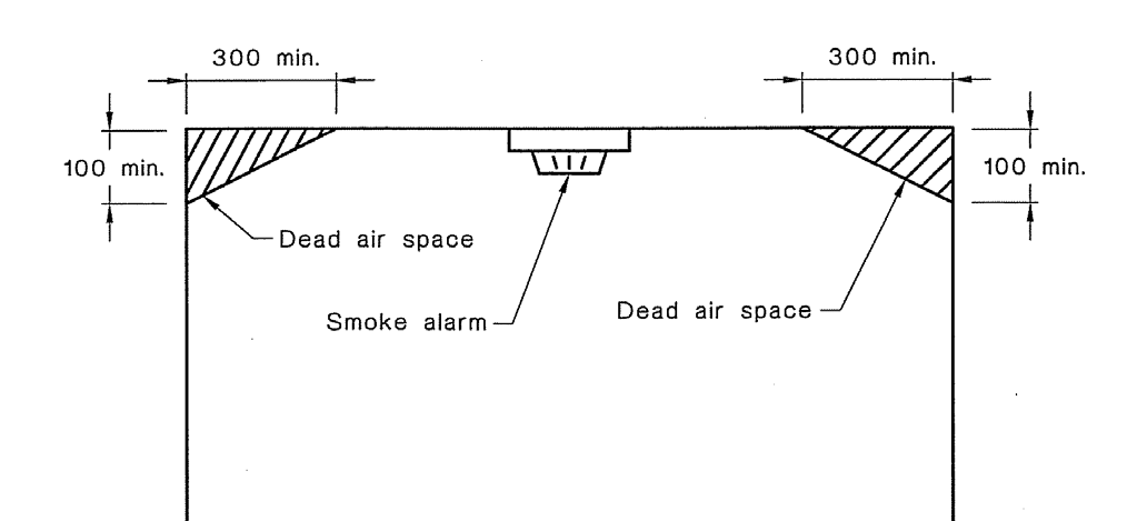
Flat ceilings
Smoke alarms need to be situated on (or near) the
ceiling for optimum detection of smoke in a fire
situation.
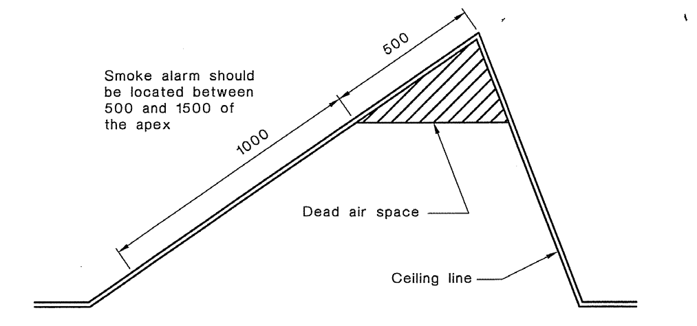
Sloping ceilings
Alarms must be located on the high side of ceiling
where the slope is > 1:8.
Page 54
September 2022
AC3601.17 (v.2)
In
stairwells, smoke alarms must be located so that
rising smoke in the stairwell is not restricted from
reaching the alarm by a door or obstruction, (alcove,
vaulted ceiling, beam, etc).
Smoke alarms must be at least 300mm clear of any
light fitting and not located in a dead air-space.
AS 1670.6 gives instructions for the physical location of smoke alarms. Observance of the manufacturer’s
instructions is important to ensure smoke alarms are mounted correctly.
Internal stairs and landings
Al stairs must be installed so that a minimum head height of 2.0m is achieved. Landings are required at the
top and bottom of every flight of stairs except where there is a fall of less than 600mm in which case the
landing can be omitted. If a landing is provided the minimum length is 900mm.
Stair
Maximum pitch
Maximum riser
Minimum tread width
height
Service, minor private
47
220
220
Secondary private
41
200
250
Common & main private
37
190
280
Accessible
32
180
310
Riser height and tread depth for all steps in any one flight must be uniform with an allowable tolerance of ±
5 mm. The triangular opening formed by the riser, tread, and bottom rail of the barrier on a stair shall be of
such a size that a 150 mm diameter sphere cannot pass through it
If 3 or more steps are present a handrail must be fitted; handrails must be graspable and provide sufficient
room to prevent knuckles touching any adjoining surface. The height of a handrail is 900mm minimum and
1.0m maximum and is measured vertically, from the pitch line or stair nosing.
A barrier must be provided to landings where there is a fall of more than 1.0m.
• detached dwellings and stairs and ramps and their landings 900mm within household units of multi-
unit dwellings
• balconies and decks, and edges of internal floors or mezzanine floors 1000m
Heights are measured vertically from finished floor level (ignoring carpet or vinyl, or similar thickness
coverings) on floors, landings and ramps. On stairs the height is measured vertically from the pitch line or
stair nosing.
If glazing is installed at the bottom of a flight of stairs, the glazing must be safety glass.
Ceiling space
The ceiling space must be checked regardless of whether or not insulation has already been sited, this is
because insulation may well have been fitted at say pre-line when light fittings, etc were not yet in place.
Each ceiling space within different levels of the building must be accessed and inspected. Manholes must
be provided for each level of the building, additionally access maybe provided through an external wall into
a roof space. The minimum size for an access panel is 600mm x 500mm.
Page 55
September 2022
AC3601.17 (v.2)
Insulation must be installed so that it fits neatly within the cavity formed by the truss or ceiling joists, it must
not cover light fittings. Where downlights are installed a cone must be fitted over the fitting to provide
protection and allow air-flow. Similarly, insulation must be kept clear of flues and other heat sources in the
ceiling space. Note that it is a requirement under NZS4246 that a label is fixed to the roof truss or access
hatch, denoting the R-values of the insulation that has been installed.
If ducting is installed, the ducting must be laid straight and not be superfluous, i.e. coiled up. Ducting must
be secured around the extraction unit and discharge via a gril e outside the building envelope, usually via
the eaves.
Electrical cables and pipes should be neatly clipped and supported on framing.
If water storage heaters are located in the ceiling space the maximum capacity is 150 litres. The water
storage heater must be supported on a framed floor and be seated over a load-bearing wall and requires a
minimum of 350mm clearance to the roof above. The floor must be a minimum of 1.2m square and 20mm
thick and be nailed at 300mm c/s.
A safe tray must be fitted under the unit and seismic restraints are required. The ceiling access must be
large enough to allow the cylinder to pass through it both at installation and replacement.
Attached garages
If the garage is attached to the house and forms part of the thermal envelope it must be insulated, this
includes the exterior walls and ceiling space above. If the garage is not part of the thermal envelope but
there is a habitable floor above, the ceiling space must be insulated.
Whilst it is not necessary to install smoke alarms in garages, it is recommended that they be installed where
they are attached to the house.
If the garage contains a laundry space, the floor and walls of the space must be lined with an impervious
covering to allow for cleaning. (Refer section on laundries above)
Garage door rebates must be formed in a manner that prevents surface water entering the interior of the
building or damaging framing and linings. The most common fault with garages is that ground levels are
built up too high and the jamb and framing of the opening is damaged as a result of water ingress. These
must be formed in a manner to protect both the framing and cladding.
Balconies / parapets on upper levels
Balconies and parapets are probably one of the most at risk weathertightness features and must be
thoroughly inspected. If the barrier or parapet has been formed with a solid barrier the horizontal surface
must be fitted with a 15 degree slope and capped with a metal capping.
Under no circumstances can handrails or balusters be mounted directly on top of the horizontal surface of a
barrier or floor as this places too much stress at the point of attachment and wil result in damage to the
membrane. Al such fixings must be on a vertical face. The height of a barrier is measured vertically from
finished floor level and must be a minimum of 1000m high.
Al gutters must be a minimum of 300mm wide and 75mm deep and fitted with at least 2 outlets and an
overflow. Outlets must be protected from infiltration of debris by fitting a grate over the top of them.
Overflows must be installed at least 50mm below flood level and located in a visible position so as to warn
of potential problems. Overflows must be 1.5 times the size of the outlet as per NZBC: E2 (8.5.10).
Page 56
September 2022
AC3601.17 (v.2)
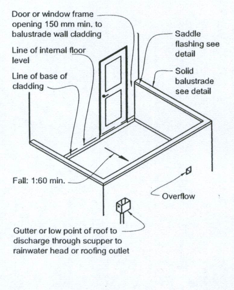
Balcony showing outlet and overflow
Detail of outlet through wall
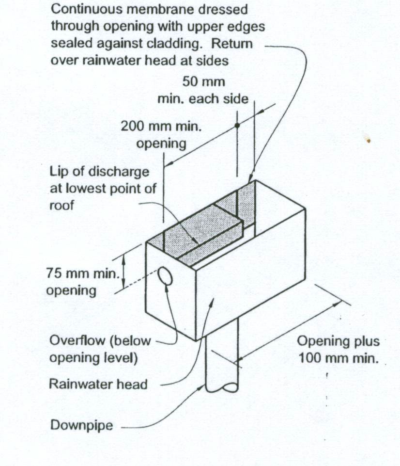
If the discharge point is through a parapet or balustrade then the scupper must be 200mm wide and 75mm
high and formed with a lip to shed water away from the cladding.
Balcony floors must be fitted with at least one outlet and one overflow installed at least 50mm below flood
level and located in a visible position so as to warn of potential problems. Outlets must be protected from
infiltration of debris by fitting a grate over the top of them.
Finished floor / roof levels must be maintained to prevent flooding and damage to claddings: -
• 35mm minimum clearance from the bottom edge of the
wall cladding to
roof cladding or finished
deck level
• enclosed deck - 100mm step down from
inside floor to the
finished deck surface
• cantilevered deck - 50mm step down from
inside floor to the finished deck surface but only if deck
surface is
timber-slatted
The floor must have a 1:30 slope formed to drain water away from the building. If a cavity system has been
installed check to ensure that vermin proofing has been installed.
Building exterior
Walk around the building carefully checking each elevation to ensure it matches the on-site layout. Ensure
any changes have been captured by either the minor or amendment process. If not, these must be
addressed now.
External stairs / pergolas
Al external stairs and pergolas must be constructed to withstand a life of 15 years. It is essential that a
12mm air-gap is provided between the cladding and the decking or pergola to prevent problems with moisture
ingress due to friction between the two structures.
Al bolts passing through timber must be fitted with a 3mm x 50mm x 50mm square washer and all fixings
must be of appropriate durability. Al such penetrations must be appropriately detailed on the plans
demonstrating weathertightness (air-gaps, flashings, seals, etc).
Page 57
September 2022
AC3601.17 (v.2)
Barriers on external stairs must be at least 1.0m high and where a landing is provided it must be a minimum
of 900mm long. Landings are required where there is a height difference of 600mm or more.
If 3 or more steps are present a handrail must be fitted, handrails must be graspable and provide sufficient
room to prevent knuckles touching any adjoining surface. The height of a handrail is 900mm minimum and
1.0m maximum and is measured vertically, from the pitch line or stair nosing.
Riser height and tread depth for all steps in any one flight must be uniform but are permitted to have a
tolerance of ± 5 mm. The triangular opening formed by the riser, tread, and bottom rail of the barrier on a
stair shall be of such a size that a 150 mm diameter sphere cannot pass through it
Steps and landings must be constructed of materials that are fit for purpose and be slip resistant.
In residential situations an access route is defined as one which the general public have access to and
includes walking surfaces such as decks, patios and steps leading up to the main entrance. These surfaces
must have a mean coefficient of friction of not less than 0.4. Refer to D1: Access for acceptable surfaces.
Note figures from the Accident Compensation Commission show that many of the accidents that happen in
a home are a result of someone slipping or falling from decks and steps.
Ground levels
The finished floor level to ground level for claddings is:
Cladding
Paved
Unpaved
Brick veneer
100mm
150mm
Other claddings
150mm
225mm
Under no circumstances may finished floor to ground level distances be compromised.
Where the site is sloping, provision for drainage on the downhil slope must be provided either by way of a
retaining wall with drainage in behind or a cut-off drain. Where the site is sloping and provision for a cut-off
drain has been made the minimum clearance between the land and the cladding is 450mm.
Where provision for level access is required from a concrete floor slab to exterior paving E1/AS1 provides
for a drainage channel to be installed between the building and the paving to drain water.
The channel must have a minimum depth of 150mm, a maximum length of 2.0m and a fall of 1:200 along
the length of the channel to a drainage outlet.
Page 58
September 2022
AC3601.17 (v.2)
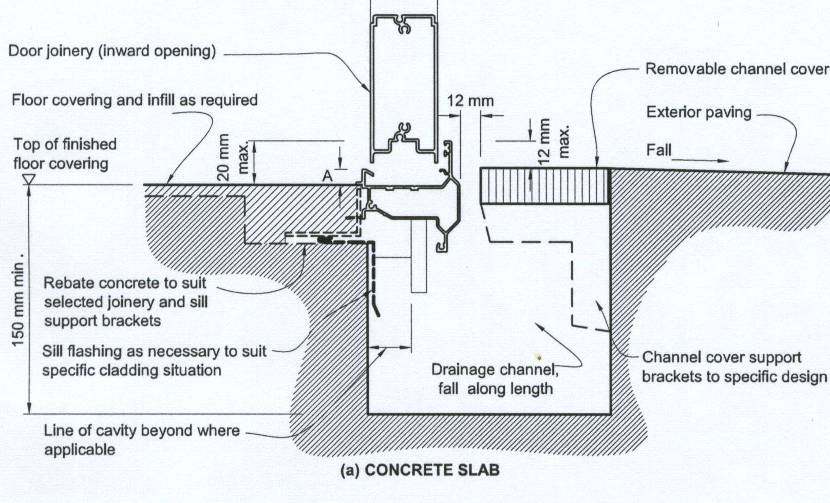
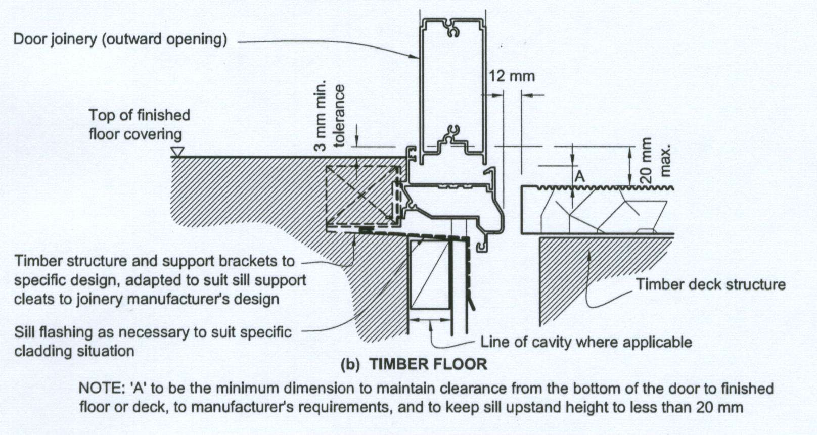 Drainage channels
Concrete floor
Timber floor
Drainage channels
Concrete floor
Timber floor
The channel should be fitted with a removable grate with continuous gaps of 12mm. Paving must fall away
from the building at a slope of 1:40. Although the acceptable solutions state the maximum length of the
channel should be 2.0m, however most garage door openings wil exceed this. The length of the channel
maybe increased at this point to suit. However, make sure that water cannot enter the garage or the framing
either side of the opening. In all other situations, the maximum length is 2.0m. Al other systems are
alternative solutions and require formal approval via an amendment.
Using your mirror check to make sure the underside of the jamb and cladding at this point have been sealed
and painted to protect the timber and cladding.
Retaining walls
If retaining walls have been constructed on site and are not part of the building consent application, the
maximum height permissible is 1.5m without a surcharge. Check the drawings and height of any retaining
walls to confirm that this is the case.
Page 59
September 2022
AC3601.17 (v.2)
When checking retaining walls ensure that a cess-pit has been installed to take surface water runoff and that
the drain is shown on the as-built plan.
If consent was not required for the retaining wall but one has been instal ed, it is good practice to note this
on the inspection records. When making your notes, identify where the structure is located and what you
have observed. It would also be prudent to take a photo for record-keeping purposes.
Finally, when checking retaining walls you must consider the location of the retaining wall in terms of access
and safety from falling. If the retaining wall is on a driveway, a barrier must be installed. Similarly, if it
supports land and paving leading to the main entrance of the house and there is a fall of 1.0m or more a
barrier complying with the provisions of F4 wil be required.
Wall cladding
Review the file and check that the claddings as specified have been installed as per plan. Compare each
elevation checking ground levels, cladding type and window sizes and openings. If there are any changes
whatsoever these must be dealt with via a formal amendment.
Undertake a thorough check to ensure that the building is weathertight. Al penetrations must be sealed with
a durable flashing and sealant. Flashings must deflect water away from the cladding.
Al waste water and vent pipes should be firmly fixed at 1.2m maximum c/s; brackets should be placed over
a rubber washer or flange to cushion the impact between the two materials, all fixings should be appropriate
for the environment and installed with sealant to prevent water ingress. The pipe should be installed with a
PVC flange sealed against the cladding and the junction between the pipe and flange sealed.
Al meter boxes (gas and electrical) must be flashed with the flashing extending across the top and down the
sides of the appliance to shed water away from the cladding.
If alarms and electrical wiring for lights, etc have been installed, these too must be flashed in a similar manner
and all fixings inserted into sealant to prevent water ingress. Where electrical cables are installed through
polystyrene the cable must be sleeved to prevent plasticiser migration. (PVC electrical cables undergo
plasticiser migration when in contact with polystyrene. This causes the polystyrene to shrink away from the
cable and cable insulation to become brittle).
If monolithic claddings have been used, the plaster must be finished and painted behind the fascia. Where
spouting from a lower storey is located adjacent to an upper storey wall, ensure that the spouting and
cladding have a minimum 20mm clearance to allow for drainage.
Where pergolas or decks have been affixed to the cladding these must be instal ed in a manner which
provides for a 12mm air-gap. Note that a building consent is not required for decking if it is less than 1.0m
in height or pergolas if they are less than 10m2 in area.
If consent was not required, it is good practice to note whether pergolas and decks have been installed if
they have not been detailed on the plans. When making your notes, identify where the structures in question
are located and what you have observed. It would also be prudent to take a photo for record-keeping
purposes.
Roof cladding
If you cannot get access to the roof, stand back from the property and inspect for damaged tiles or roofing
and take note of whether TV aerials or satellite dishes have been installed. Sometimes on 2 or more storey
houses it wil be possible to view or access the roof from an upper storey window; in any event, access
should be provided so that all flashings and falls on roof parapets, roof decks, and gutters can be checked
and confirmed.
Page 60
September 2022
AC3601.17 (v.2)
If you cannot access the roof during the final inspection, you must note this on the inspection records and
discuss the reasons for this with your Team Leader before approval can be considered.
Valley gutters must not be used on roofs with a pitch of less than 8 degrees or 12.5 degrees if the gutter is
160 - 250mm wide, changes in direction are not permitted. Roofing should overlap the valley gutter by
100mm and have a clearance of 50mm above the gutter.
Where a concrete tile discharges into an internal gutter the tile should overhang at least 50mm and have a
clearance of 50mm to the bottom of the gutter. If the gutter is located beside a parapet or wall, a 100mm
clearance is required between the roof cladding and the cladding on the wall.
Where profiled metal roofing discharges into an internal gutter the roofing requires a 50mm overhang and
the gutter must be 300mm minimum wide and 70mm minimum deep.
Internal gutters must be installed with a fall of 1:30; seams should be avoided in a gutter but if installed are
not permitted within 1.0m of the drainage outlet. Where the roof is > than 40m2 ventilation wil be required to
prevent heat build-up in the void below.
Drainage outlets must be placed clear of any structural members and installed in a position to achieve
maximum catchment. The minimum size outlet is 75mm diameter or if rainwater discharges into a rainwater
head via a scupper, the minimum width must be 300mm.
If discharge is through a parapet or balustrade then the scupper must be 200mm wide and 75mm high and
formed with a lip to shed water away from the cladding.
Al internal junctions must be supported using a 450 timber fil et to relieve stress to the membrane and be
extended a minimum of 150mm up the face of the wall. Al gutters must be provided with an overflow installed
at least 50mm below flood level.
On eaves and verges, the membrane must be dressed over the substrate which must extend at least 50mm
over the wall below and be secured, capped or over-flashed to prevent moisture ingress. Refer to figure 61
in E2/AS1 for further details.
Al flashings should be dressed down into the tiles or corrugations of the roofing material. Al roofing material
must extend out over the spouting in a manner that wil prevent wind driven rain getting into the roof cavity.
Al roof penetrations must be flashed with durable and compatible components; sealant is added as a
secondary measure only, the flashing or boot being the primary mechanism for achieving weathertightness.
Membrane roofs must have a fall of no less than 2 degrees; note this is more than the Acceptable Solutions
require however this is Councils policy. Under no circumstances may a downpipe discharge onto a
membrane deck or roof.
Downpipes
Downpipes must be evenly spread around the building to ensure rainwater is safely transferred from the roof
into the drainage system. Depending on the type of spouting used, the maximum run between downpipes
is 9.0m but wil depend on the manufacturer’s requirements. If internal fascia has been used this wil need
to be significantly increased to ensure that water is safely removed. Note that whilst the provision of
overflows helps this does not redress the problem.
Many problems with leaky buildings can be attributed to a lack of downpipes resulting in water spil ing from
the spouting into the eaves and making its way back into the framing cavity. The minimum size downpipe is
75mm.
Page 61
September 2022
AC3601.17 (v.2)
Where downpipes discharge from an upper roof to a lower one, a spreader must be fitted. A maximum
catchment area of 25m2 only, is permissible.
Under no circumstances can the spreader discharge water
into roof laps. The spreader must be capped at either end and holes positioned to discharge into the pan or
trough of the roof cladding.
Under no circumstances can the downpipe discharge water into membrane decks.
Note that if a spreader is used on a concrete tile roof, the tiles must be laid over a 1.0m square of building
paper.
Gully traps – G13 NZBC
Every building used for housing must have at least one gul y trap positioned so that the top of the gully dish
is no less than 150 mm below the overflow level of the lowest sanitary fixture served by the drainage system,
which must be located in a visible position and installed so that surcharge cannot enter into or under the
building.
Al gully traps shall be constructed to prevent the ingress of surface water and foreign bodies likely to cause
a blockage. Gullies must be located within the legal boundary of the land on which the building is erected,
and the overflow level of the gully dish must be no less than:
• 25 mm above paved surfaces, or
• 100 mm above unpaved surfaces, and
Gullies must also have:
• a grating that wil allow surcharge
• a minimum outlet pipe diameter of 100 mm
• a water seal depth of at least 65 mm
• at least one discharge pipe discharging to the gully trap to avoid water seal evaporation
• waste pipes that discharge to the gul y trap should be arranged to permit easy cleaning of the gul y
trap
• waste pipe outlets located at least 20 mm above water seal level, and at least 20 mm below the
grating
• the top of the water seal no more than 600 mm below the top of the gully dish, and
• adequate support from bedding and backfil ing with:
o concrete no less than 75 mm thick surrounding the entire gully dish and which is separated
from the building foundation, where the gully trap is likely to be damaged, or
o compacted bedding material
o a minimum of 600 mm clear access space above the gully dish for cleaning purposes
Overflow relief gullies (ORG) – AS3500
At least one ORG or disconnector gully must be installed on a drain except where the lowest fixture is located
on a floor that is 3m or more above ground surface level at the point of connection to the sewer.
A minimum height of 150mm must be maintained between the top of the ORG riser and the lowest fixture
connected to the drain. The minimum height between the top of the gully riser or the invert of the overflow
pipe and the surrounding ground level shall be 75mm except where the gully riser is located in a paved area
where it must be finished to a level that does not allow water ingress.
Gullies must be: -
• self cleansing
• supported on a 100mm bed of concrete
Page 62
September 2022
AC3601.17 (v.2)
• have the top of the gully protected from damage by means of a concrete surround (minimum width
of 100mm around and 100mm deep below ground)
• have a grating to relieve surcharge
• have a permanently maintained water-seal provided by
o discharge from a waste fixture or floor waste gully
o water from a tap located over the gully
o discharge from a waste stack no > 5 floors in height (discharging below the grate but above
the water seal)
Note that WCs and surface or roof water may not discharge into a gully. Waste water discharge pipes must
either discharge into a gully trap or a discharge stack; WC’s must discharge directly into a drain.
Discharge stacks and vents – G12 NZBC
A discharge stack may serve as a vent if the distance from the water trap to the stack is 1.5m for 80mm
diameter and 6.0m for 100mm diameter pipes. A discharge stack may also serve as a fixture vent so long
as the fixture vent is the top most connection to the stack.
Where 2 branch drains enter the discharge stack at the same level a Y junction with a 900 angle must be
used. Where 2 branch drains enter the discharge stack at different levels they must not be connected within
the restricted zone (within 200mm) and be fitted at a 450angle to the stack.
Fixtures discharging to a gully trap must be independently vented. Vents must be connected to the discharge
pipe between 75mm – 3.5m of the gully trap and terminate outside the building no less than 900mm from
any opening in the building.
Where the discharge pipe is greater than 3.5m to the gully trap an air-admittance valve must be fitted, which
cannot be smaller in diameter than the vent pipe that it serves.
Air admittance valves shall be installed in an upright (vertical) position at least 100mm above the weir of the
fixture trap and in a location that is accessible for maintenance and inspection. It must be protected from
likely damage and instal ed so that adequate air can enter the valve. Ventilated openings shal be provided
for air admittance valves installed within a wall space, with the free area of the openings being not less than
1.5 times that of the vent pipe.
Other fixtures maybe vented to: -
• a vertical or graded fixture vent pipe
• an ascending graded or vertical fixture vent pipe connected to a branch vent pipe, a discharge stack
vent or a relief vent
The connection must be made no less than 50mm above the overflow level of the sanitary fixture it serves.
Fixture vent pipes and branch vent pipes must extend upwards from the point of connection to the fixture
discharge pipe to the open atmosphere, or to an air admittance valve, with a gradient of not less than 1:80.
Where terminating to the open atmosphere vent pipes must be fitted with a cowl to prevent birds and vermin
entering the pipe.
In order to prevent any foul air entering the building vents must terminate
• 3.0m above ground level
• 600mm above and 3.0 m below and horizontally of any window openings
• 150mm above any roof
• 3.0m above, below and horizontally of any deck, which provides pedestrian access
• 600mm above any eave
• 5.0m in any direction of an air-intake
Discharge stacks and vents – AS3500
Under AS3500 there are two types of ventilated systems.
Page 63
September 2022
AC3601.17 (v.2)
•
Fully vented system
this is where each fixture is independently vented, except traps permitted to discharge to a FWG
(note that a discharge pipe on a FWG wil already be vented)
•
Fully vented modified system
each branch or discharge pipe connected to a stack is vented and some individual fixtures trap vents
are omitted (this occurs when 2 or more fixtures discharging to a pipe or vent are vented by one or
more group vents)
Discharge pipes must be 40mm diameter minimum and cannot be less in diameter than the fixture it serves.
WCs must have a minimum vent size of 80mm and have no more than 2 WC’s connected to it.
Trap vents
Trap vents are required in the following circumstances: -
Basins and bidets
• the vent must be connected between 75mm and 600mm from the crown of the fixture (no change of
direction is permitted)
Other fixtures
• the vent must be connected between 75mm and 1.5m from the crown of the fixture except that where
an S-trap is fitted, or a bend is fitted to a P-trap, the connection must be 300mm from any bend at the
base of the vertical section
A stack vent may serve as a trap vent for a fixture provided that: -
• the fixture is the highest connected to the stack
• the distance from the weir of the trap to the stack complies with the requirements listed in the 2
paragraphs above
• loading in fixture units are not exceeded
The minimum size of a trap vent is: -
Fixture trap
Vent
40mm
32mm
50 – 100mm
40mm
Trap vents must extend upwards above the flood level rim of the fixture and vent to the open air.
A single vent pipe maybe used for two or more fixtures if: -
• a P-trap is used
• the discharge pipes are connected at the same level they are fitted with a Y junction at a 900 angle
or a junction with opposed sweep entries
• the vent pipe is sized for the larger trap
• the distance from the weir does not exceed 75mm and 600mm for bidets and basins and 75mm and
1.5m for other fixtures
Branch vents are sized as follows: -
Page 64
September 2022
AC3601.17 (v.2)
Size of branch discharge pipe
Size of branch vent
40
32
50
40
65
40
80
50
100
50
150
80
Branch vents must be connected above the flood level rim of the highest fixture connected to it and vent to
the open air.
Relief vents
Relief vents must be installed on any stack where one or more floors separate the floor levels of the highest
and lowest branch pipe connected to the stack or where a stack is offset at less than 450 to the horizontal.
Relief vents must be connected to the stack below the lowest connection at an angle of 450 and extend
upwards to the open air. The minimum size of a relief vent is 40mm but should be no large than the stack it
serves.
Venting of stacks
Vents must continue upwards to the vent cowl undiminished in size and be instal ed at a minimum grade of
1.25% so that condensation or other liquids that form in or enter the vent wil drain to the system.
Vents shall terminate in the open air and in a location not less than: -
• 600mm above any opening that is within 3.0m horizontally of the vent
• 150mm above the roof
• 3.0m above any deck which provides pedestrian access that is within 3.0m horizontally of the vent
• 2m above or 600mm below any chimney or similar opening that is within 3.0m horizontally of the vent
• 5.0m in any direction of an air-intake
• 600mm above the eave, coping or parapet that is within 600mm horizontally of the vent
Where a vent is connected to a graded section of a discharge pipe it must be connected downstream of the
fixture or trap.
Location of vent pipes
Pipes must be located so that they: -
• do not impede the operation of a door, window or other aspect relating to the operation of a building
• have adequate protection from damage
• are as close as practicable to the wall of the building
• are at least 100mm away from any electrical cable
• are not less than 50mm clear from any other pipework
• are not located above a potable water storage tank
Page 65
September 2022
AC3601.17 (v.2)
 Waste storage
Individual units which form part of multi-unit developments are checked in accordance with the residential
checklist. In addition to a normal residential situation, multi-unit developments require a space where waste
/ rubbish can be stored.
Examples of trade waste include:
• storage of garbage in apartment buildings
The facilities must provide for the safe and hygienic col ection, holding, treatment and disposal of the waste:
- • interior surfaces impervious (floor drain and tap for washing down the space)
• space totally enclosed and separated from habitable spaces
• space well ventilated (natural or mechanical ventilation provided)
• space protected from high temperatures and direct sunlight, which could hasten purification – no
direct sunlight from the north
• space screened or enclosed to reduce visual impact
• access for building occupants complies with D1, and
• access for rubbish collection vehicles complies with D1
Other issues
Multi-unit developments may also include other items such as lifts, public telephones, reception areas, etc.
Refer to commercial section for this information.
Solid fuel heating
Refer to solid fuel heating section for this information.
Page 66
September 2022
AC3601.17 (v.2)
Document Outline
- Cladding
- Inspection requirements
- General information:
- Wall cladding
- Timber weatherboards
- Horizontal boards
- Vertical boards
- Solid plaster and stucco - Definitions of solid plaster and stucco
- Control joints
- Reinforcement
- Pipes and service penetrations
- Plaster
- Painting
- Producer statements construction
- Brick veneer
- Inspection requirements
- General requirements:
- Type of veneer
- Corrosion zone
- Building paper
- Cavity
- Ties
- Mortar
- Flashings
- Overhang
- Weepholes
- Vent holes
- Plastering brick veneer
- Timber sub-floors
- Gable end
- Returns
- Control joints
- Lintels and head flashings
- Sills
- Jamb flashings
- Ground levels
- 2-storey brick veneer
- Plumbing
- Inspection requirements
- General information
- Water saving devices
- Spouting and downpipes
- Equipotential bonding
- Domestic sprinklers
- Solar water heating
- Solar collector
- Storage cylinder:
- Frost protection:
- Installation
- Plumber’s details
- Deck Membranes (Tanking)
- Inspection requirements:
- General information:
- The Building Code defines waterproof or waterproofing as: -
- Substrate
- Penetrations
- Internal gutters
- Insulation
- Ventilation
- Supporting documentation
- Wet area
- Membranes
- Inspection requirements:
- General information:
- The Building Code defines waterproof or waterproofing as: -
- For wet areas the following performance requirements should be met:
- Wall and floor lining materials must meet the following criteria:
- Waterproofing should extend
- Suitable impervious wall linings include:
- Flexible Sheet Vinyl - as a wall lining
- Tiling - as a wall lining
- Rigid Sheet Shower Linings
- Suitable impervious floor coverings include:
- Supporting documentation
- Flood or flow test
- Drainage
- Septic tanks
- Inspection requirements:
- General information:
- On-site waste water disposal
- Location to existing or proposed buildings
- Location near waterways / natural hazards
- Vegetative cover
- Maintenance
- Procedure for testing and commissioning the system
- As-built plans and records
- Solid Fuel Appliance
- Inspection requirements:
- General information:
- Hearths
- Existing chimneys
- Free-standing units
- Clearances around the unit
- Wet-backs
- Flues
- Alarms
- Residential final
- Commercial final
- Inspection requirements:
- General information
- Accessibility
- Accessible route
- Openings in buildings
- Lifts
- Accessible counters
- Public telephones
- Listening systems
- Other facilities
- Wet areas
- Accessible showers
- Toilets (W.C)
- Accessible toilets
- Kitchen
- Grease traps
- Backflow devices
- Atmospheric vacuum breakers (AVB)
- Pressure vacuum breakers (PVB)
- Double check valves (DCV)
- Trade waste
- Dangerous goods
- Measures to mitigate trade waste spills include:
- Heating, ventilation and air-conditioning (HVAC)
- Ceiling spaces
- Building exterior
- Equipotential bonding
- Ground levels
- Retaining walls
- External wall cladding
- Roof cladding
- Downpipes
- Drainage:
- Specified systems
- Section 363 and compliance schedules
- Re-clad
- Inspection requirements:
- General information:
- Complex reclad consents are defined as:
- Processing
- Quality assurance programme
- Project Methodology
- Site or floor plan
- Elevations
- Record sheets
- Photographs
- Inspection
- Preconstruction
- Strip off
- Remedial works inspection
- Targeted repairs
- Moulds and fungi
- Relocatable buildings
- Inspection requirements:
- General information
- New buildings
- Existing buildings
- Footings
- Remedial work
- Other inspections
- Final inspection
- Fire damage
- Inspection requirements:
- General information:
- Flood damage
- Inspection requirements:
- General information
- Section 5
- Appendices
- Appendix I - Planning issues
- Appendix 2 Legislation
- Appendix 2(a) Schedule 1: Exempt Building Works
- Appendix 2(b) Schedule 2:
- Please refer to Building (Specified Systems, Change the Use, and Earthquake Prone Buildings) Regulations 2005/32
- Appendix 3 Standards
- Appendix 8 Acronyms
- Appendix 9 Methamphetamine / Amphetamines
- Appendix 10 - Metric conversion table