

(1982)
Act
Weather-tightness and Durability Requirements
for School Property
Information
For
Project Managers
Designers
Official
Contractors
Principals and Boards of Trustees
the
Ministry of Education
Revised - June 2014
under
Amended – August 2014
Released
Weather-tightness and Durability Requirements – August 2014
1 | P a g e
Contents
INTRODUCTION
A
Background
B
Scope
C
Compliance
D
How to use this document
E
Materials and features whose use is Restricted
F
Weather-tightness / Durability Checksheet
G
Sign-off Report
H
Review Process
I
Submission to the Ministry
J
Responsibility for Weather-tightness and Appropriate Design
K
Amendments to Design, Materials Substitutions etc
Section 1
SURFACE WATER
1.1
Overland Flow Paths
Section 2
RETAINING WALLS
2.1
Retaining Walls as Separate Structure
2.2
Retaining Walls as Integral Part of Building Envelope
Section 3
CONCRETE SLAB ON GRADE
Section 4
SUSPENDED TIMBER FLOORS
4.1
Sub-floor areas
4.2
Sub-floor fixings
4.3
Slatted Decks
4.4
Flooring
Section 5
EXTERIOR WALLS
5.1
Blockwork
5.2
Concrete
5.3
Timber or Steel Framing – Design Principles
5.3.1 Timber Treatment and Fixings
5.3.2 Plywood treatment
5.3.3 Cavity Construction
5.3.4 Top Venting
5.3.5 Air Barrier
5.3.6 Flexible Wall Underlay
5.3.7 Rigid Sheet material
Section 6
CLADDING
6.1
Ground Floor Cladding Selection
6.2
Cladding As Bracing
6.3
Services penetrations through Walls
under the Official Information Act (1982)
6.4
Metal Wall Cladding
Released
Weather-tightness and Durability Requirements – August 2014
2 | P a g e
Section 7
ROOF
7.1
Metal Roofing
7.1.1 Roof pitch
7.1.2 Material Thickness
7.1.3 Condensation and Thermal Bridging
7.1.4 Roof Underlay
7.1.5 Penetrations
7.1.6 Eaves
7.1.7 Flashings
7.2
Membrane Roofing 7.2.1 Roof design
7.2.2 Roof-water Outlets
(1982)
7.2.3 Overflows
7.2.4 Testing
7.2.5 Roof-space Ventilation
7.3
Masonry Tiles
Act
7.4
Parapets
7.5
Internal Gutters
7.5.1 Gutter Capacity
7.5.2 Gutter Outlets
7.5.3 Gutter Overflows
7.5.4 Testing
7.6
Valley Gutters
Section 8
EXTERIOR JOINERY
Section 9
BALCONIES
Information
Section 10 JUNCTIONS WITH EXISTING BUILDINGS
Section 11 EXPOSED STRUCTURAL ELEMENTS
Section 12 DURABILITY
Official
Appendix A – Weather-tightness / Durability Check Sheet
the
under
Released
Weather-tightness and Durability Requirements – August 2014
3 | P a g e
Introduction
A.
Background
In recent years a large number of school buildings have suffered building envelope weather-
tightness failure and the Crown faces a significant cost for remedial work.
The most common causes have been identified and this
Weather-tightness and Durability
Requirements for School Property publication (the
Requirements) is the result and it:
focuses on those aspects of construction that have contributed to the failures and for
which the Ministry now has specific requirements
prohibits the use of some materials or features and restricts the use of others
replaces the Ministry’s previous Weather-tightness requirements for schools April (1982)
2011 publication which focussed on the major risks to school property,
covers all design features and materials that are known to create weather-tightness
or premature durability failure.
Act
The Ministry has engaged the services of a
Building Enclosure Specialist (BES) to peer-
review the construction details of projects that contain specific materials or features to help
ensure that the building’s envelope is weather-tight and appropriately durable.
Contact details of the BES may be obtained from any Ministry Regional office.
B.
Scope
These Requirements apply to:
general school buildings ie administration, teaching spaces, gyms, halls
buildings to a maximum of 2 storeys (with height measured from lowest ground level
adjacent to the building). Buildings above this height shall have the following
Information
submitted to BES
o full envelope construction details
o structural Design Features Report.
They do not apply to:
ancillary buildings (ie storage sheds, non-integral garages)
covered walkways, canopies, shelters etc.
The envelope of specialist buildings (ie enclosed swimming pools) requires design input from
Official
personnel who can demonstrate appropriate experience with the building type. Full envelope
construction details for these buildings shall be submitted to the BES.
the
C.
Compliance
Building envelopes shall not contain materials or features that are
not permitted.
Materials or features which are not permitted, are shown with red background .
Where the building envelope includes materials or features whose use is
restricted, full
under
construction details for these items shall be submitted to the BES.
Materials or features which are restricted, are shown with blue background .
Where the design of any item does not comply with any clause or detail in these
Requirements, full construction details for these items shall be submitted to the BES.
Released
D.
How to use this document.
This document is intended for Project Managers, Designers, Principals and Boards of
Trustees.
Weather-tightness and Durability Requirements – August 2014
4 | P a g e
If you are…
You should…
understand the technical aspects of these
Requirements
Project Manager
ensure Designers are aware of, and comply with them
at completion of Detailed Design, receive Appendix A from
Designer together with
o construction details of materials or features whose
use is Restricted
o
construction details for any item that does not comply
with any detail or clause in these
Requirements
submit these details to the
BES
ensure that documentation has been modified to address
(1982)
any concerns identified by the
BES before calling tenders
receive Weather-tight / Durability Review Sign-off Report
from the
BES
submit the report to MoE prior to calling tenders
Act
ensure that the Contractor is aware of the specific areas of
the project where these
Requirements apply
understand these
Requirements
Designer
at completion of Detailed Design, provide Project Mgr with
o Appendix A
o construction details of materials or features whose
use is Restricted (with Technical info if appropriate)
o construction details for any item that does not
comply with any detail or clause in these
Requirements (with Technical info if appropriate)
Information
modify the documentation to address any concerns
identified by
BES
ensure that the Contractor is aware of the specific areas of
the project where these
Requirements apply
have a general understanding of these
Requirements
Principal or BoT
and the responsibilities of The Project Manager and
Official
member
Designer
ensure that Project Manager is aware of them
understand the Concept, Developed and Detailed Design
the
stages of project documentation
understand the effect that selection of materials / components
can have on future maintenance budgets
under
Released
Weather-tightness and Durability Requirements – August 2014
5 | P a g e
E.
Materials and Features whose use is Restricted
Prior to commencing
Developed Design stage
, Designer shall alert the Project Manager, to
any materials or features whose use is
Restricted by these
Requirements, which will form
part of the design.
At completion of
Detailed Design, Designer shall provide the Project Manager with finished
construction details of these elements for submission to the BES for a Weather-tightness /
Durability Review.
To avoid delays, all information required for the BES to fully understand details, junctions
etc, must be provided. Materials, flashings, wraps, air seals, etc shall be fully described,
detailed, dimensioned etc.
(1982)
Designers may wish to engage with the BES earlier in the design process to determine:
information required
any criteria that will reduce the likelihood that details will need to be modified
the time that is likely to be required for the Review (so that this is anticipated in the
Act
overall project timeline).
After assessing the information submitted, the BES may identify aspects considered at-risk,
which require further consideration / modification by the Designer, to improve weather-tight
or durability performance. Rationale supporting the requirement and guidance to resolve the
risk, will be provided.
F.
Check Sheet.
The Weather-tightness / Durability Check Sheet (Appendix A) shall be completed by the
Designer and submitted to the Project Manager at completion of Detailed Design.
Information
G.
Sign-off Report.
At completion of the Review process, the BES will provide the Project Manager and Ministry
Weather-tight Coordinator with a Weather-tightness / Durability Sign-off Report:
summarising the review process that was undertaken
confirming that the Designer’s responses to items raised, were satisfactory
Official
confirming that there are now reasonable grounds to believe that the design of
features reviewed, complies with sound weather-tightness practice and where
specific materials have been used, they should have appropriate durability.
the
H.
Review Process.
Designer
submits Appendix A to Project Manager
identifies (from the
Requirements) those materials or features requiring a Review
and submits finished construction documentation for them, to Project Manager.
under
Project Manager
forwards documentation to Building Enclosure Specialist together with:
o School name
o School ID
o Project name
o Project ID (provided my MoE).
Building Enclosure Specialist
Requests approval to commence Review from Ministry’s Weather-tight Coordinator.
Ministry’s Weather-tight Coordinator
Released
Authorises BES to undertake Review.
Building Enclosure Specialist
Assesses details and identifies any aspects requiring further detail / information /
consideration / amendment.
Weather-tightness and Durability Requirements – August 2014
6 | P a g e
Designer
Amends materials / features as necessary to the Building Enclosure Specialist’s
satisfaction.
Building Enclosure Specialist
Provides Weather-tightness / Durability Sign-off Report once there are reasonable
grounds to believe envelope is weather-tight and specific materials should be
appropriately durable.
I.
Submission to the Ministry.
The Project Manager shall submit the following information to the appropriate Ministry
personnel, when seeking approval to call tenders:
sufficient documentation to confirm that the project complies with (and does not
exceed) the scope of work approved by the Ministry
(1982)
copy of Weather-tightness / Durability Check Sheet (Appendix A)
copy of Weather-tightness / Durability Sign-off Report from BES, for those projects
that have required a Review.
Act
J.
Responsibility for Weather-tightness and appropriate Design.
The Ministry encourages innovative designs but buildings with complex floor plans,
complex roofs or complex elevations:
cost more
introduce greater risk of weather-tightness failure.
Designers shall:
provide building envelopes which minimise:
o irregular or complex junctions
Information
o junctions between different cladding materials and profiles
o features that will affect the durability of elements or materials
select envelope materials that will:
o minimise maintenance requirements
o minimise whole-of-life costs
o deliver appropriate performance throughout the life of the building.
Official
The ability to:
remove contaminants that will affect a materials durability
maintain the envelope to ensure warranty requirements are met
the
are important considerations for Designers.
While the involvement of the Building Enclosure Specialist is provided as an aid to ensuring
appropriate performance, overall responsibility for detailing an envelope that is weather-
tight under all weather conditions and materials perform appropriately over the life of the
building, remains solely with the Designer.
under
K.
Amendments to Design, Materials Substitutions etc
The Project Manager shall draw to the attention of all personnel involved with the
Released
construction, that any party who makes changes to any aspect of the contract
documentation (Specification / Materials selection / Construction details) relating to the
building’s envelope, without obtaining the Designer’s prior approval in writing, wil assume
Weather-tightness and Durability Requirements – August 2014
7 | P a g e
full responsibility for the weather-tightness and durability performance of the feature and that
of any abutting construction.
This process of substitution may involve re-submitting to the BES for further review.
The designer should take the following into account when considering a substitution:
level of detail provided on the substitute product
shop drawings (where appropriate) to show how the installation will be carried out
product characteristics (strength, air leakage, assembly etc) as appropriate
the risk associated in departing from a known product (or one which has been
thoroughly researched at the design stage).
It is particularly relevant to the selection / substitution of a branded window system where the
designer has implied (but not nominated) a brand by the CAD details used and the
contractor wishes to nominate its own preference, which may not be an equivalent.
(1982)
A precise specification is needed in the contract documentation.
Act
Information
Official
the
under
Released
Weather-tightness and Durability Requirements – August 2014
8 | P a g e
Section 1:
Surface Water
1.1
Overland Flow Paths
To protect against water damage when drainage systems become blocked or over-loaded,
and in all developments where siteworks or re-contouring of the ground is being
undertaken, configure site levels to provide stormwater overland flow paths away from
buildings.
Always be aware of the cut ground levels (CGL) and the finished ground levels relative to
the buildings lowest RL or finished floor level (FFL).
Expert advice from a Civil Engineer may be required.
(1982)
Section 2:
Retaining Walls
Act
2.1
Retaining Walls as a Separate Structure
A retaining wall shall be provided:
where the level of adjacent ground is above that required in Section 3 below.
The retaining wall shall be separated from the exterior wall of the building by a
minimum distance of 1.5 metres. The ground between the retaining wall and the
building shall meet the surface finish, height and fall requirements of NZBC.
where the ground below a suspended timber floor is excavated as per clause 4.1
below.
Information
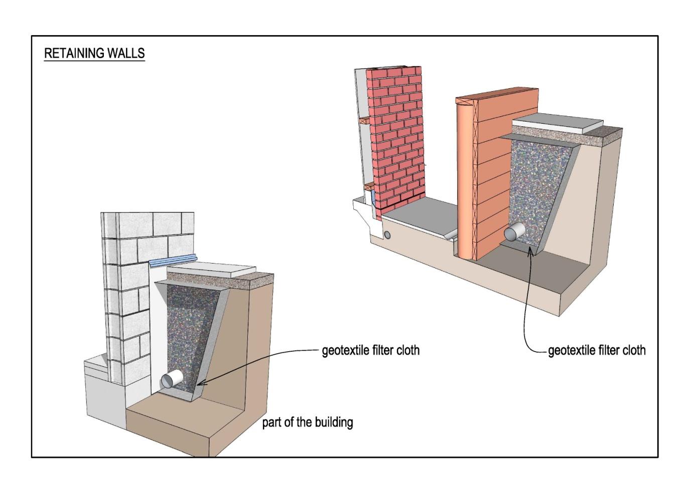
2.2
Retaining Walls as an integral part of Building Envelope
Liquid applied products are not permitted as a means of waterproofing retaining
walls that form part of the building envelope.
Using the wall of a building to retain adjacent ground is a Restricted design
element.
Official
Where a separate structure is not provided and the external wall of the building retains the
adjacent ground, water ingress shall be prevented as follows.
Apply proprietary sheet tanking-membrane to exterior of wall:
o
the
possessing a Code-Mark certificate
o holding valid BRANZ Appraisal certificate.
Protect:
o top of membrane with a flashing chased into wall and sealed
o surface of membrane with proprietary drainage mat, fibre cement or
polystyrene sheet.
under
Provide:
o perforated subsoil drain with:
invert at the highest point 150mm (min) below floor level
fall of 1:200(min) to silt-trap end-outlet
access to the ends for water-jet cleaning
o polypropylene filter cloth to separate existing ground from backfill material
o clean and free draining backfill material
o filter cloth to separate any topsoil placed over backfill material.
Released
Direct surface water away from the wall with mowing strip (refer Section 3 below) and
if necessary provide a surface drain to its edge.
Weather-tightness and Durability Requirements – August 2014
9 | P a g e
(1982)
Act
Section 3:
Concrete Slab on Grade
Information
Slot-drain channels are not permitted at the base of external walls
(except as noted below)
There is a risk that dampness in channels may raise the moisture level in the adjacent wall
cavity.
Where new buildings are constructed with a concrete floor slab, the finished floor level
(above the finished level of adjacent ground - 150 or 225mm as per NZBC) shall be set so
Official
that drainage channels or concrete nibs are not required.
Drainage channels (complying with NZBC) may be fitted at Accessible Entries where
adjacent paved surface is raised to provide level-entry threshold (≤ 20mm).
the
The total building perimeter including landscaped areas, shall have a minimum 500mm wide
strip of permanent paving set 150mm below FFL with 30mm fall away from building. An edge
drainage channel (complying with Fig 7.12 NZS 3604:2011) shall be provided if this gradient
is not maintained for 1m
Finished surface of landscaped areas (FGL) shall be no higher than the outer edge of the
under
permanent paving.
Section 4:
Suspended Timber Floors
Released
4.1 Sub-floor Areas
Where the ground floor is supported on piles, subfloor areas:
shall not be excavated or set below adjacent ground unless an impervious retaining
wall is employed
Weather-tightness and Durability Requirements – August 2014
10 | P a g e
shall be graded or provided with surface drainage to prevent water ponding
shall be overlaid with 250 micron polyethylene sheets with all joints lapped and taped.
Sheets shall be fitted tight to piles (and perimeter walls where present).
Polythene may be omitted where subfloor ventilation (fully compliant with requirements of
NZS3604) is provided on all 4 sides of the building (note restrictions imposed in 4.3 below).
Vents in subfloor foundation walls shall be vandal resistant with care taken to ensure that the
required free-ventilation area is achieved.
4.2 Sub-floor Fixings
All fixings for sub-floor areas shall be Type 304 stainless steel.
4.3 Slatted Decks
Where a slatted deck (ie rain permeable) is positioned adjacent to a piled building, provide a
(1982)
sub-floor wall (without ventilation openings) to separate it from the subfloor area to prevent
dampness from below the deck entering the building sub-floor area. (Polythene ground
overlay will be required under the building as ventilation is not provided on all 4 sides).
Act
4.4 Flooring
In any situation where there is a risk of intermittent dampness in sub-floor areas, plywood
flooring shall be used (refer clause 5.3.2 for treatment).
Section 5:
Exterior Walls
The following wall types are not permitted for building envelopes:
Walls that are curved.
Information
Walls that have a primary structure other than timber, steel, concrete or
concrete block.
The following wall type is a Restricted design element:
Walls that are not vertical.
Official
5.1
Blockwork
Honed-face structural concrete blockwork is not permitted for exterior walls of
the
interior spaces.
Honed-face blocks rely on a clear coating to display their unique appearance, but the on-
going integrity of the clear coating cannot be readily visually assessed.
Honed-face block veneer may be used, but must be protected by an anti-graffiti coating to
minimum height of 3m.
under
Stack-bonded concrete blockwork is not permitted for exterior walls of interior
spaces.
Laying in this manner has not proven to be as crack-resistant as running (stretcher) bond.
Concrete blockwork forming the exterior walls of interior spaces is a Restricted
Released
design element.
Additional Observation by a Structural Engineer is required at all stages of block laying and
grouting.
Weather-tightness and Durability Requirements – August 2014
11 | P a g e
The base course of blockwork shall be set in a rebate 50 -100mm below finished floor level.
All blockwork shall be laid and solid-filled under the supervision of a Brick and Block
Licensed Building Practitioner.
A rain-screen cladding fixed over a cavity:
is mandatory on the exterior face of blockwork which supports a concrete upper floor
is encouraged in other circumstances, because blockwork is considered prone to
transfer moisture when, over time, cracks occur through settlement, coatings degrade
etc.
All blockwork (without a rain-screen) forming the exterior walls of interior spaces, shall be
coated on the exterior face with a pigmented (ie not clear-coated so that the integrity of the
coating can be visually assessed) acrylic high-build elastomeric water-proofing paint system
(formulated to fill surface pores, bridge fine cracks etc) to achieve a dry film-build of 180
microns minimum.
(1982)
Additional Observation and film thickness measurement is required during the application of
the high-build membrane, to ensure appropriate film-build is achieved.
Act
5.2
Concrete
The use of concrete (precast or cast insitu) for exterior walls is a Restricted
design element.
Walls constructed of this material do not require a rain-screen on cavity.
Walls constructed to be watertight by fully complying with
CCANZ CP 01:2014 Weathertight
Concrete and Concrete Masonry Construction cl 4.5 Watertight Concrete:
must be protected by an anti-graffiti coating to minimum height of 3m
may be clear coated with Silane or Siloxane water repellent sealers to protect and
Information
enhance remaining surfaces.
Clear coatings will require regular re-coating to maintain the integrity of the surface.
All other concrete walls shall be coated on the exterior face with:
a pigmented acrylic high-build elastomeric paint system to achieve a dry film build of
180 microns
Official
a pigmented acrylic paint system to achieve a dry film build of 80 microns.
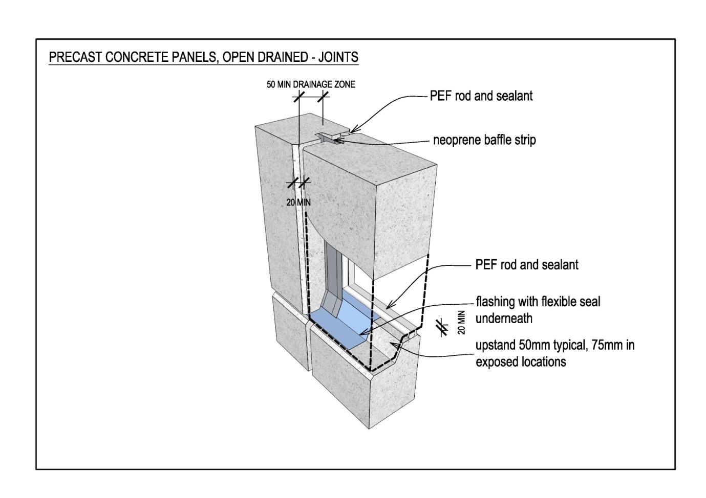
Precast panels shall be minimum 125mm thick.
the
under
Panel joints shall be:
front sealed with the joint able to drain at the base (ie finishing above surrounding
paving level)
back sealed (to create effective air-seal and establish pressure moderation).
Released
Weather-tightness and Durability Requirements – August 2014
12 | P a g e
(1982)
Act
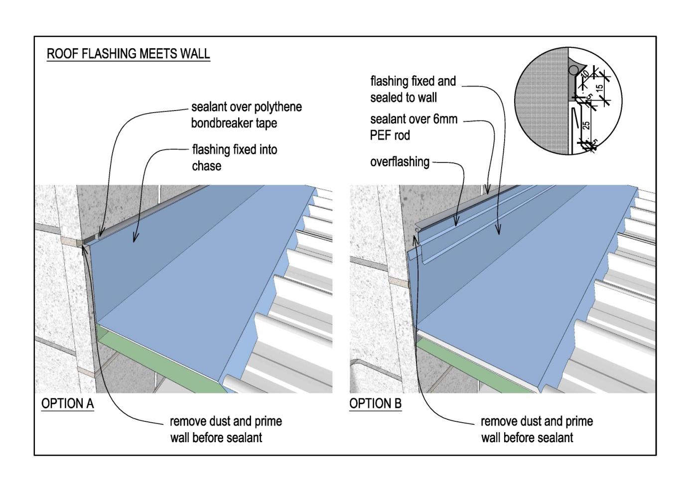
The flashing of roofs (or other surfaces) which abut precast panels, require particular
attention (particularly at vertical panel joints which are inevitably recessed).
Information
Option B (shown below) is less preferred because sealant is exposed to elements with
consequential degradation over time.
Official
the
under
Released
Weather-tightness and Durability Requirements – August 2014
13 | P a g e
 5.3
Timber or Steel Framing – Design Principles
5.3
Timber or Steel Framing – Design Principles
These principles apply without exception, (irrespective of the cladding material chosen), to:
new buildings
extensions to existing buildings.
Refer below for circumstances where a cavity may be omitted when altering an existing
building.
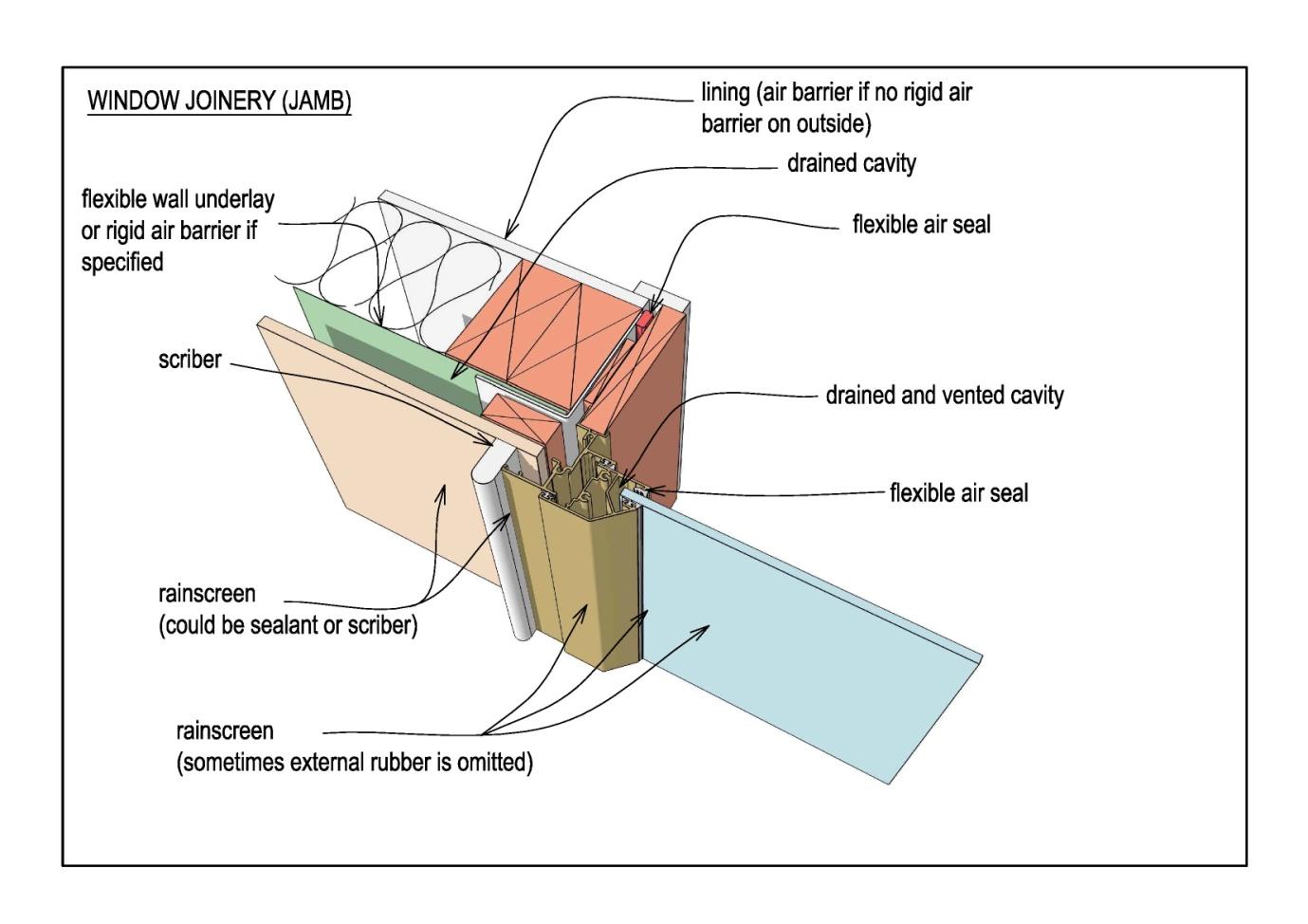
All timber and steel framed exterior walls shall be detailed to incorporate.
Exterior Rain-screen cladding
to deflect all / majority of moisture.
Drained cavity with top ventilation
drained to allow any moisture that penetrates the rain screen to escape
top vented to assist drying by allowing air movement, to aid evaporation.
(1982)
Internal air barrier
to reduce air pressure differential between the drained cavity and exterior, to prevent
Act
air pressure driving moisture into the building.
Information
Official
the
under
An
Exemption from the requirement to provide a cavity may be given for alterations to existing
buildings that have been constructed without a cavity, such as where:
windows are being removed and in-filled to match an adjacent surface
existing cladding is being replaced with an alternative type.
In these circumstances:
Released
any new wall framing that is required shall be H3.2
the permitted cladding type shall be determined by the Risk Score for that wall, given
by NZBC E2 / AS1 Table 3.
Weather-tightness and Durability Requirements – August 2014
14 | P a g e
Window or cladding change to existing buildings constructed without a cavity, is
a Restricted design element.
5.3.1 Timber treatment and fixings
In all situations where copper-bearing preservatives are used (ie CCA, CQ [previously
ACQ] CuAz) to achieve required treatment levels (ie H3.2), fixings shall be stainless
steel (nails, staples, bolts etc).
(Galvanised steel will react with timber treated with copper-bearing preservatives and must not be
placed in contact with it).
(1982)
5.3.2 Plywood Treatment
Act
LOSP treated plywood is not permitted . .
Plywood used as sarking shall have thickness determined by span, with minimum:
15mm under profiled metal roofs
17mm as substrate for membrane roofs
20mm as substrate for decks.
Plywood shall have the following minimum treatment and fixings shall be stainless steel.
50 year durability
Information
Use
Exposure
Treatment
Sub-floor foundations
In contact with ground
H5
Rigid air barrier
Protected / risk of moisture penetration
H3.2 CCA
Bracing - Sub-floor
Protected / exposed to ground atmosphere
H1.2
- Exterior walls
Protected / risk of moisture penetration
H3.2
Official
- Interior walls
Protected
None
Flooring – Dry areas
Protected / exposed to ground atmosphere
None
– Wet areas
Protected / exposed to ground atmosphere
H3.1
the
Sarking
Protected / risk of moisture penetration
H3.2
Support (valley boards etc)
Protected / risk of moisture penetration
H3.2
15 year durability
Exterior finishing
Exposed / not in ground contact
H3.2
Cladding
Exposed / not in ground contact
H3.2
under
Exterior stairs, floor surfaces
Exposed / not in ground contact
H3.2
etc (easily replaced)
Interior Stairs
Protected
None
5 year durability
Interior finishing, joinery etc
Protected
None
(easily replaced)
Released
5.3.3 Cavity Construction
Cavities shall be:
compartmentalised to provide separation from cavities on opposite sides of walls (ie
where parapets occur) and on adjacent walls
o to avoid undue wind pressure differentials
Weather-tightness and Durability Requirements – August 2014
15 | P a g e
o to allow pressure equalisation / moderation to occur.
separated from roof, subfloor and sub-deck areas
o to allow pressure equalisation / moderation to occur
o to avoid transfer of moisture from the ground
top vented on buildings up to 2 storeys in height (refer below).
Cavities may be continuous for a maximum of 2 storeys in height.
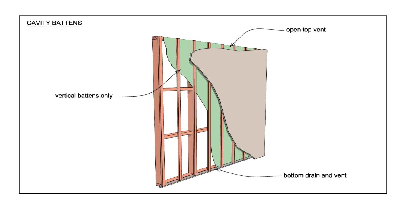
Battens to provide horizontal support for cladding, flashings or wall penetrations, shall be:
short lengths, fixed vertically with tops bevelled to shed water toward the outer face
(refer below for exemption for profiled steel fixed vertically)
installed to maintain the openness of the wall cavity (for drainage and ventilation)
positioned to support the cladding at the centres required by the manufacturer.
Where profiled steel sheets are fixed vertically, products such as Cavity Batten Systems Ltd
Cavibat may be fixed horizontally.
(1982)
Act
Information
Official
5.3.4 Top Venting
All cavities on buildings up to 2 storeys in height, shall be vented in a manner similar
the
to that illustrated below (the Ministry has obtained Determination 2013/046 to allow
top-venting).
Buildings which exceed this height:
shall only have a method of draining cavities at each floor level
shall have full envelope construction details submitted to the BES for review.
under
Released
Weather-tightness and Durability Requirements – August 2014
16 | P a g e
(1982)
Act
Information
Official
the
under
Released
Weather-tightness and Durability Requirements – August 2014
17 | P a g e
(1982)
Act
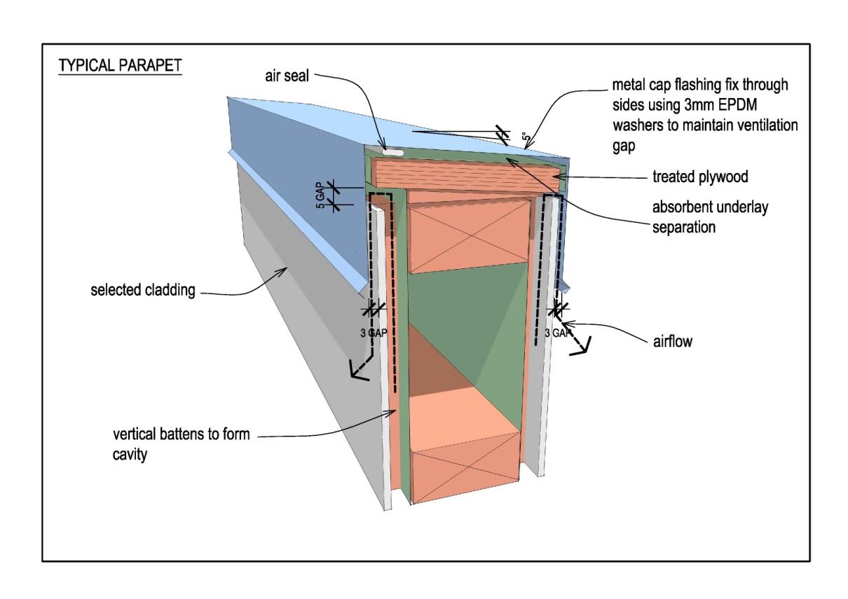
Where a parapet forms the top of a cavity, air pressure differentials between the
cavities on each side of the parapet shall be prevented by an air seal placed beneath
the parapet capping:
Information
Official
the
under
5.3.5 Air Barrier
a)
If using NZS3604 and/or E2/AS1 to assess wind exposure
Low and Moderate wind zones
The air barrier can be provided by interior wall linings provided sheet
joints and penetrations (ie switches and socket outlets) are sealed-off
Released
High, Very High, Extra High and Specific Design wind zones
Air Barrier shall be Rigid Sheet Material in accordance with NZBC
E2/AS1 Table 23.
Weather-tightness and Durability Requirements – August 2014
18 | P a g e
On external walls where no internal linings are fitted (ie gable-end of roof void),
an Air Barrier must be provided
Low and Moderate wind zones: Flexible Wall Underlay (which meets
Air Barrier requirements in E2/AS1 Table 23) may be used provided
the Underlay is not likely to be damaged. Where damage is possible
(stores, garages etc) a Rigid Sheet Material is required (as above)
High, Very High, Extra High and Specific Design wind zones: Rigid
Sheet Material is required.
b)
If undertaking a cladding pressure study to AS/NZS 1170 – install RAB
when the ULS cladding pressures obtained are above 1000 Pa.
Note: Cladding pressures include all relevant pressure coefficients and
are not ‘basic pressure’
(1982)
5.3.6 Flexible Wall Underlay
Act
The following products are not permitted :
Kraft paper (including Bitumen impregnated or Fire resistant)
Flexible Wall Underlay shall:
have a current BRANZ Appraisal
be water resistant, absorptive (hydrophobic), permeable synthetic non-woven
(Polymeric) type complying with Table 23 E2/AS1
be laid horizontally
have side and end laps of 150mm.
Information
5.3.7 Rigid Sheet Material
Rigid sheet material shall be 7mm H3.2 plywood or 6mm fibre cement in accordance
with NZBC E2/AS1 Table 23, overlaid with Flexible Wall Underlay (building wrap).
Rigid Sheet Material may be fixed to provide sheet bracing requirements.
Official
Section 6:
Cladding
the
6.1
Ground Floor Cladding Selection
Cladding at ground floor level shall be selected to withstand impact damage.
The following products are not permitted at Ground Floor level
Fibre-cement cladding less than 8mm thick (depth at grooves not counted)
under
EIFS cladding.
uPVC systems.
EIFS used in any other situation is a Restricted material.
All EIFS cladding shall:
have been tested and have current BRANZ Appraisal
be verified to E2 / VM1 (modified AS / NZS 4284 test).
Released
All Ground Floor cladding less than 16mm thick shall be provided with:
bottom-edge protection of timber or metal
external-corner protection of timber or metal.
Weather-tightness and Durability Requirements – August 2014
19 | P a g e
(1982)
Act
6.2
Cladding as Bracing
Cladding fixed over a cavity, is not permitted to be used as wall bracing.
Information
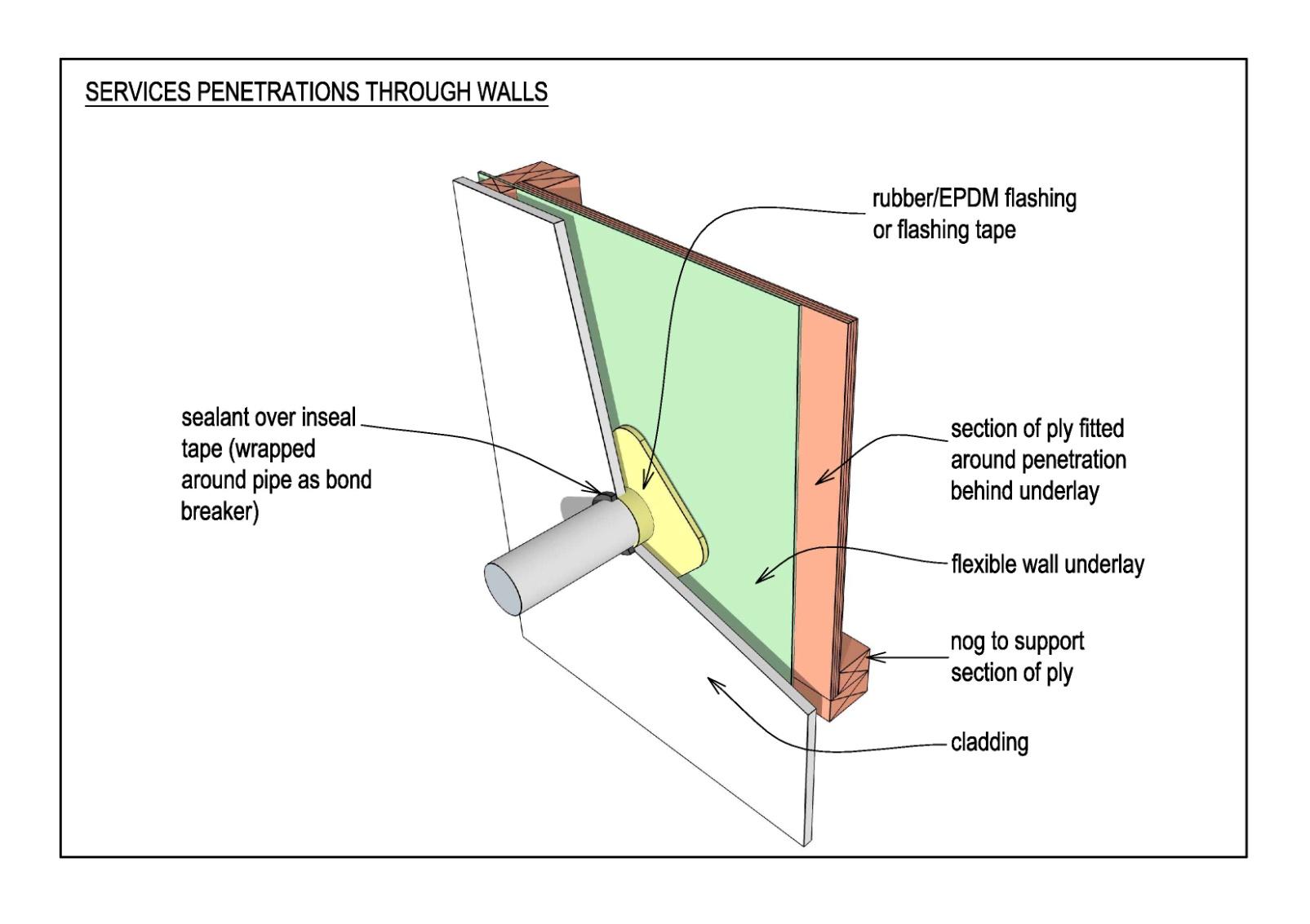
6.3
Services Penetrations through Walls
Pipes and cables which penetrate the wall cavity and cladding, shall be sealed with Vanluk
Design Ltd MG-50 or MG-100 E2 Pipe and Cable Cavity Flashing (or equivalent), as
illustrated below.
Official
the
under
Released
6.4
Weather-tightness and Durability Requirements – August 2014
20 | P a g e
Metal Wall Cladding
Except where more stringent requirements are given below, metal wall cladding shall be
detailed and installed to comply with NZ Metal Roof and Wall Cladding Code of Practice
Version 2.2 / 2012.
Section 7:
Roof
The following requirements do not apply to covered ways, canopies, shelters etc which do not
form part of the main building envelope.
Roof:
shall be simple form with generous slope and overhang
shall be designed and constructed to minimise potential for leakage
(1982)
penetrations shall be kept to a minimum
when regular maintenance is anticipated, safe access must be provided on the roof.
All joints / junctions shall be correctly lapped and shall not rely on sealant for weather-
Act
tightness.
7.1
Metal Roof
Curved metal roofs are not permitted
Climate change has resulted in more intensive rainfall and as a consequence, a conservative
approach to roof design and rainwater collection systems is required.
Except where more stringent requirements are given below, metal-clad roofs shall be
Information
detailed and installed to comply with NZ Metal Roof and Wall Cladding Code of Practice
Version 2.2 / 2012.
7.1.1 Roof pitch
The minimum roof pitch shall be as follows.
New buildings:
o trough and trapezoidal section roofs
50
Official
o corrugated roofs
12º
Replacement of existing roofs (except where these pitches cannot be achieved
without disproportionate cost and where there has been satisfactory
the
performance of the roof at the lower pitch):
o trough and trapezoidal section roofs
3º
o corrugated roofs
8º
Re-pitched roofs which will result in windows having to be reduced in height, is a
Restricted design.
under
Engage with BES at an early design stage to see if a less expensive alternative exists.
Refer to clause 7.6 below for restrictions on use of valley gutters where roof pitch is
less than 80.
7.1.2 Material thickness
The minimum Base Metal Thickness (BMT) for all steel roofs shall be 0.55 mm.
7.1.3 Condensation and Thermal Bridging
Released
The design of roof elements shall pay particular attention to preventing or mitigating the
formation of condensation in roof cavities as a result of thermal bridging and other
phenomena.
Moisture is best controlled in the spaces where it is created, by ventilation and heating
Weather-tightness and Durability Requirements – August 2014
21 | P a g e
within the space.
This is particularly important where large numbers of students are present.
BRANZ research has shown that condensation may occur on the underside of metal
roofs and on roof-space steel structural members:
when suspended ceilings are fitted
where insulation is placed on the ceiling tiles
when water vapour is likely to be present (ie from groups of students)
when surface temperature of metal roofing falls (ie during clear-sky radiation)
after periods of rain (even if timber purlins are used or timber thermal-break
battens are fitted to steel purlins).
Condensation that forms on the underside of the metal roofing is managed by the roof
underlay which:
(1982)
initially absorbs moisture, then
releases moisture to be evaporated when roof-cavity temperature rises.
Condensation that forms on steel purlins or roof-space structural members cannot be
Act
controlled.
7.1.4 Roof Underlay
The following underlays are not permitted :
Kraft paper (including Bitumen impregnated or Fire resistant)
Roof underlay shall:
have a current BRANZ Appraisal
Information
be fully supported (mesh shall comply with Safety Mesh Standard AS/NZS
4389:1996)
be separated from insulation by a 20mm air gap
be water resistant, absorptive (hydrophobic), permeable synthetic non-woven
(Polymeric) type complying with Table 23 E2/AS1
have side and end laps of 150mm
be laid horizontally (except on roofs < 80 where it may be laid vertically but
Official
all laps shall be sealed with window flashing tape):
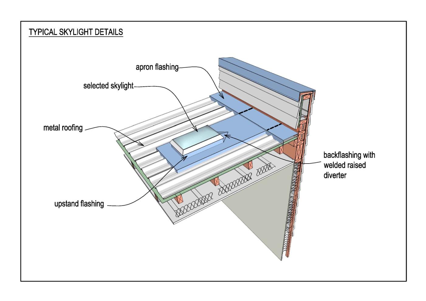
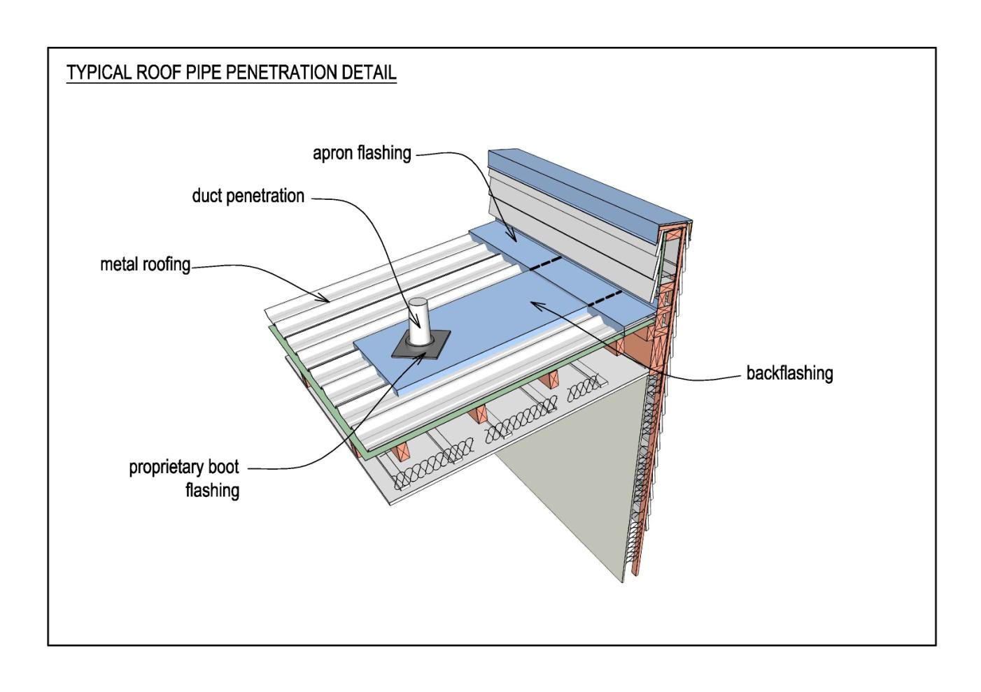
7.1.5 Penetrations
the
Penetrations shall be kept to a minimum (leaks are often associated with roof
penetrations)
the top face of large roof penetrations (ie skylights) shall be located within
2.5m of the ridgeline to minimise the length of back flashing needed from the
penetration to the ridge above it
small penetrations (ie pipes) shall be directed within the roof structure to
under
emerge at sensible locations.
Penetrations greater than 300 x 300mm shall be fully supported all round.
Refer to details below for typical vent-pipe and skylight flashing detail.
Released
Weather-tightness and Durability Requirements – August 2014
22 | P a g e
(1982)
Act
Information
Official
the
under
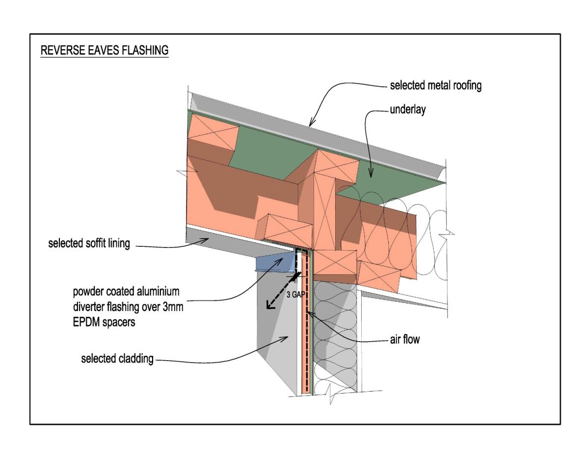
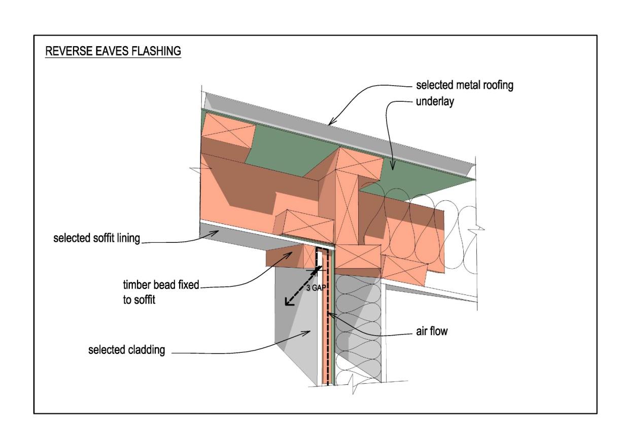
7.1.6 Eaves
The provision of generous eaves is encouraged.
Released
Refer to Section 12 Durability for eaves / overhang design considerations.
Reverse-slope eaves shall be fitted with a flashing or batten as illustrated in 5.3.4 Top
Venting (above).
Weather-tightness and Durability Requirements – August 2014
23 | P a g e
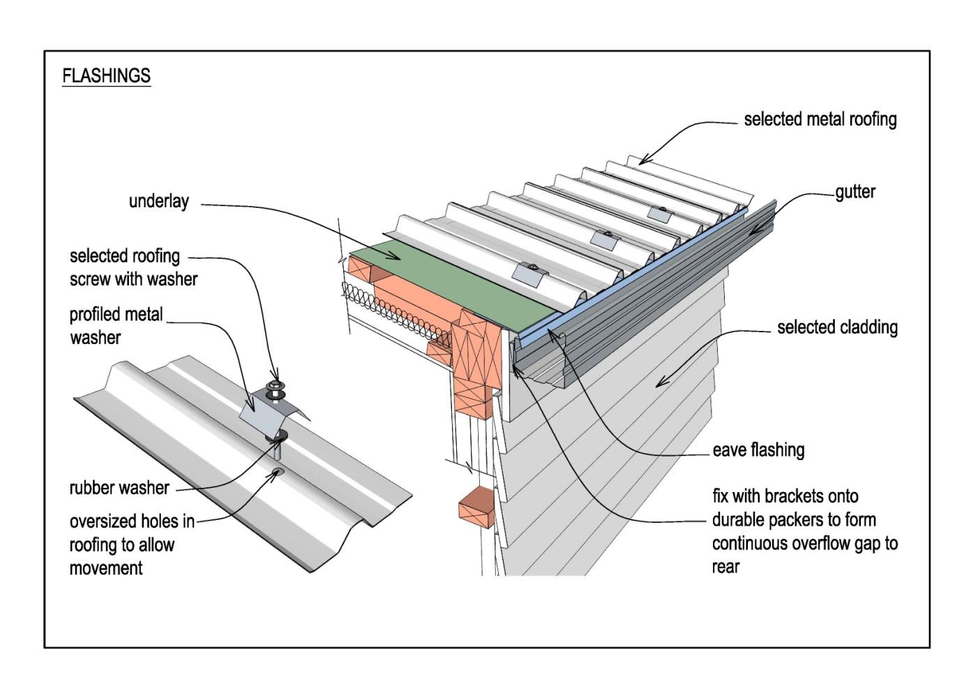
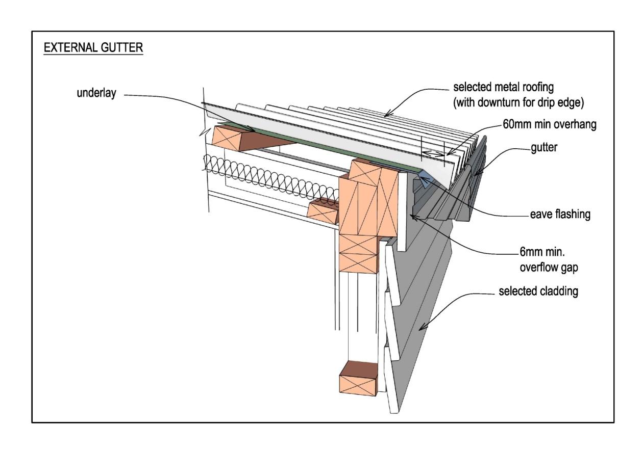
For corrugated roofing in Wind Zones Very High and Extra High (NZS 3604), provide
the eaves flashings shown below.
(1982)
Act
Information
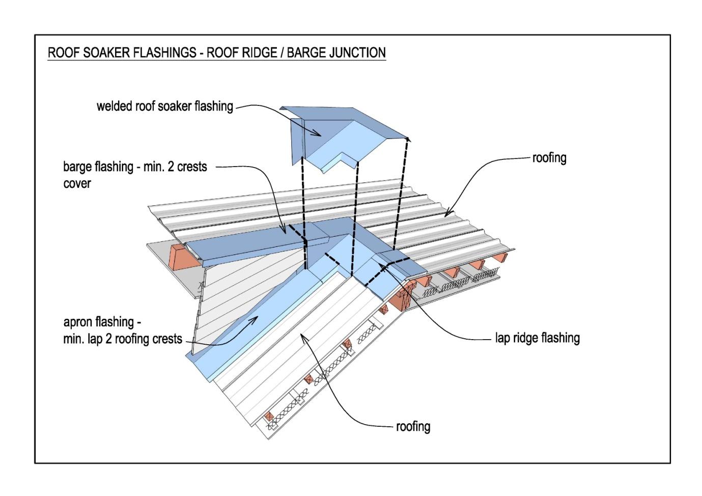
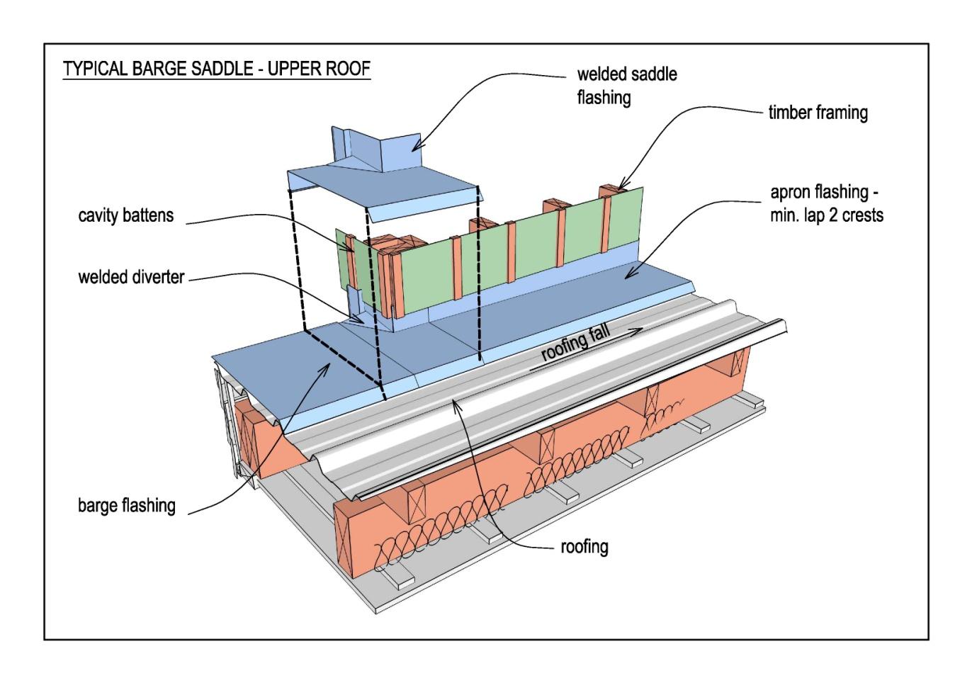
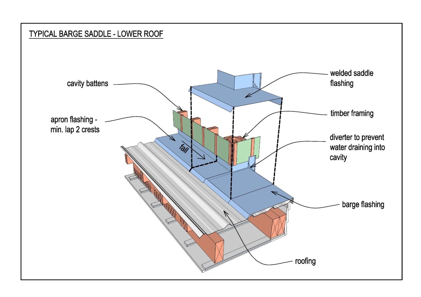
7.1.7 Flashings
Wherever possible, flashings shall be powder-coated aluminium (painted or coloursteel
flashings should be avoided, particularly in protected locations ie not rain-washed).
Complex roof junctions shall have compound flashings:
Official
1.6mm aluminium
formed to-suit and welded
painted (preferably powder-coated).
the
Raking barge flashings may have lapped joints (not welded).
Top fixing is only permitted on raking barge flashings.
Refer below for typical details.
under
Released
Weather-tightness and Durability Requirements – August 2014
24 | P a g e
(1982)
Act
Information
Official
the
under
Released
Weather-tightness and Durability Requirements – August 2014
25 | P a g e
(1982)
Act
Information
Official
the
under
Released
Weather-tightness and Durability Requirements – August 2014
26 | P a g e

(1982)
Act
7.2
Membrane Roofing
Liquid applied membranes are not permitted
The use of membranes for roofing or internal gutters, is a Restricted design element.
Information
Projects which incorporate membrane roofing require precise detailing and an increased
level of attendance and observation by the Designer at the time the substrate is fitted and the
membrane installed.
Where membranes are used they shall have:
current BRANZ Appraisal
Official
minimum 15year material warranty
5 year installation warranty.
the
Membranes shall be selected from the following types:
Butyl and EPDM rubber in accordance with E2/AS1, or
2 layer fully-bonded torch-applied reinforced modified bitumen membranes with
mineral chip finish, installed in accordance with the Code of Practice for Torch-on
Membrane Systems for Roofs and Decks, or
Synthetic plastic sheet membranes such as Thermoplastic Olefins (TPOs) and PVC.
under
Installation of the membrane shall only be by applicators licensed by the manufacturer.
Ply substrate shall be fully protected to maintain dryness until membrane is laid.
Released
7.2.1 Roof Design
Internal gutters shall be avoided whenever possible (see below for simple roof
Weather-tightness and Durability Requirements – August 2014
27 | P a g e
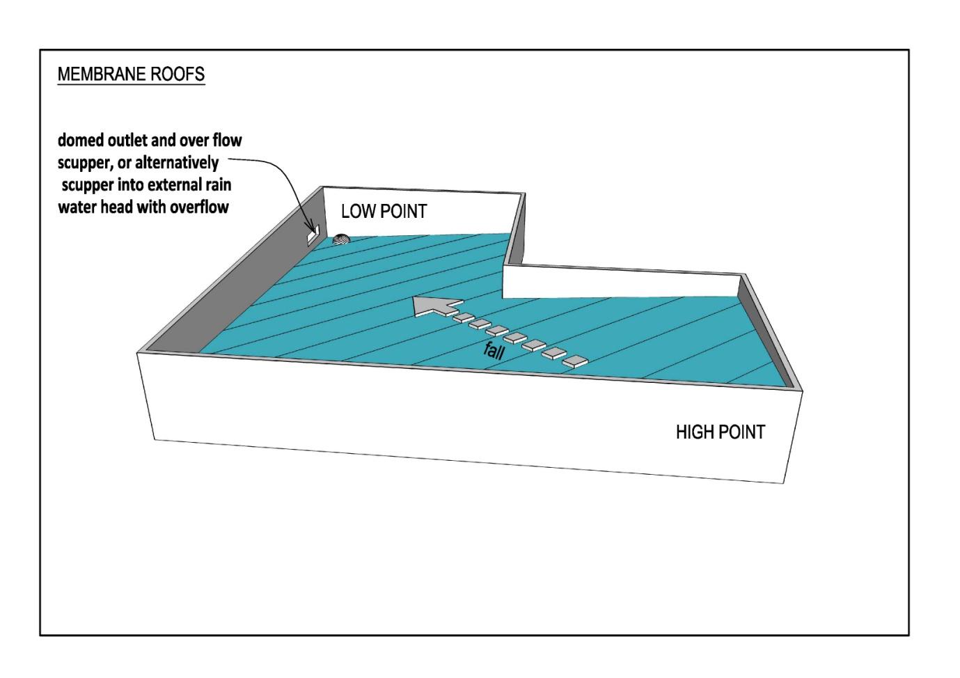
design without formed gutter).
Contract documentation shall show the levels of the high and low points of the
substrate at all edges and changes of plane. Work the levels back from the low point
of membrane at the outlet.
Membrane roofs shall have:
minimum number of sheet joints
minimum pitch of 1.50 (1:40).
(1982)
Act
Information
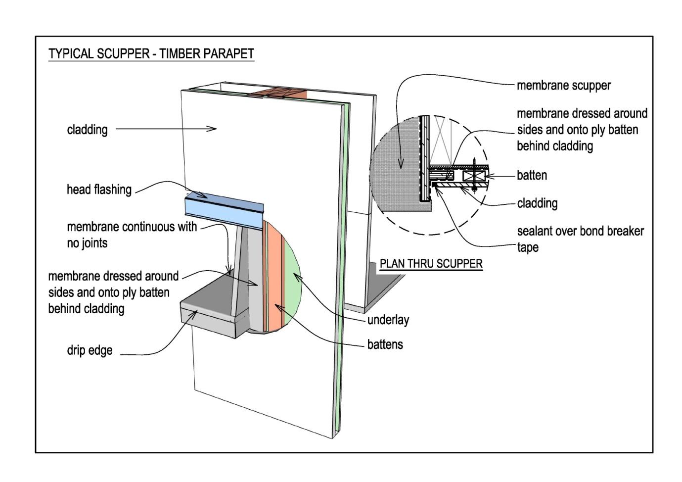
7.2.2 Roof-water Outlets
Official
The membrane shal terminate with a weir ‘drip-edge’ into an external rainwater
head.
the
Outlet capacity shal accommodate twice “1 in 50-year” rainfall intensity (ie
100mm/hr for external gutters and 200mm/hr for internal gutters).
Local rainfall intensity shall be obtained from NIWA or the Territorial Authority.
Suitable design methods are provided in E1 / AS1 and BRANZ Bulletin 537 Sizing
Gutters and Downpipes.
under
7.2.3 Overflows
Overflows shall be provided as an opening in the rainwater head and:
cross-sectional area of overflow shall be1.5 times the area required for the
outlet
height shall be set so that the overflow functions before water can enter the
structure, if the downpipe becomes blocked.
7.2.4 Testing
Released
Blocking the outlet and flood-testing to check the integrity of the membrane is
recommended before internal linings are fitted.
Weather-tightness and Durability Requirements – August 2014
28 | P a g e
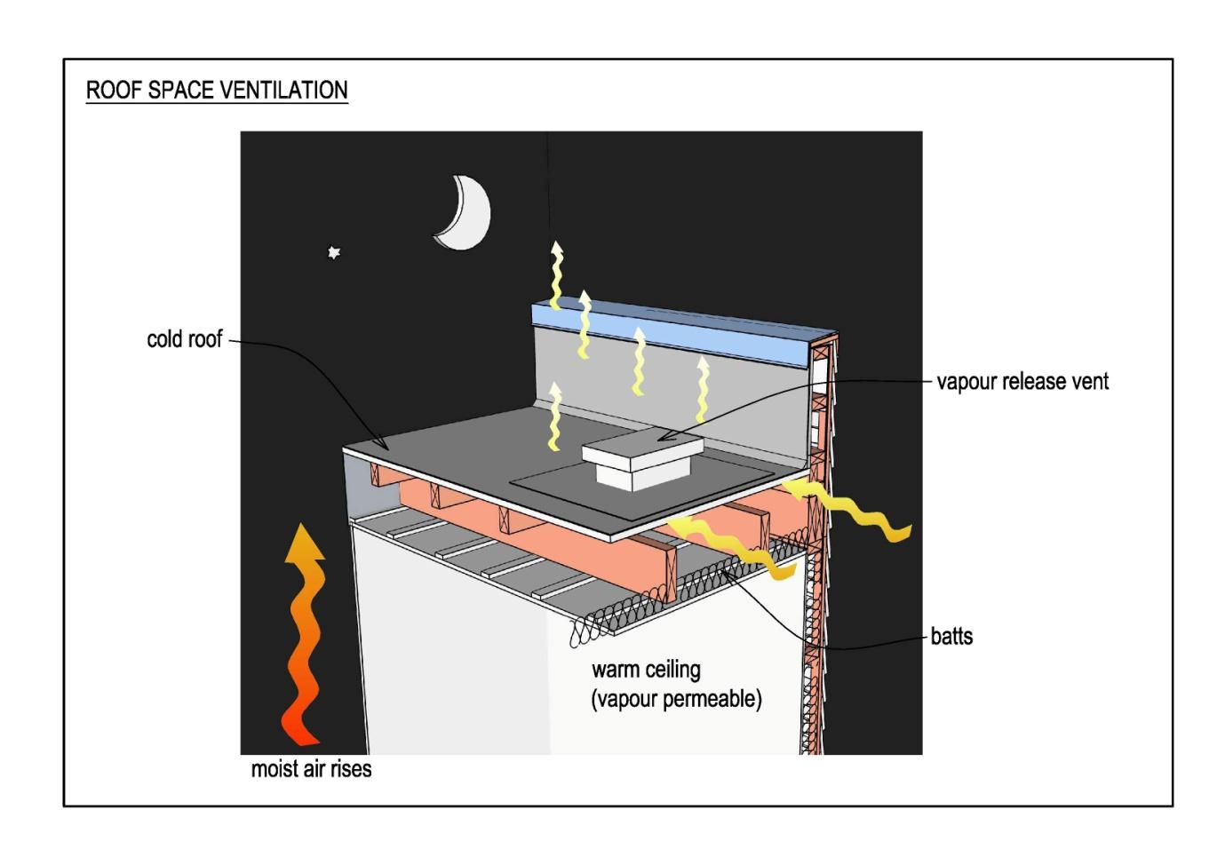 7.2.5 Roof-space Ventilation
Provide
cross ventilation between the roof-space voids below the membrane
substrate
proprietary vapour vents from the voids at 1 / 40m2 of roof area (minimum
vent area 400 mm2)
Vents shall be designed to ensure roof remains water-tight.
Any resulting reduction in R value of thermal insulation shall be taken into account.
(1982)
Act
Information
Official
the
7.3
Masonry Tiles
All masonry tile roofs shall be fitted with underlay (irrespective of pitch).
under
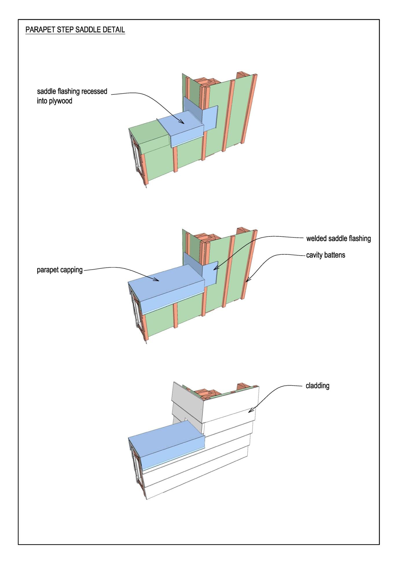
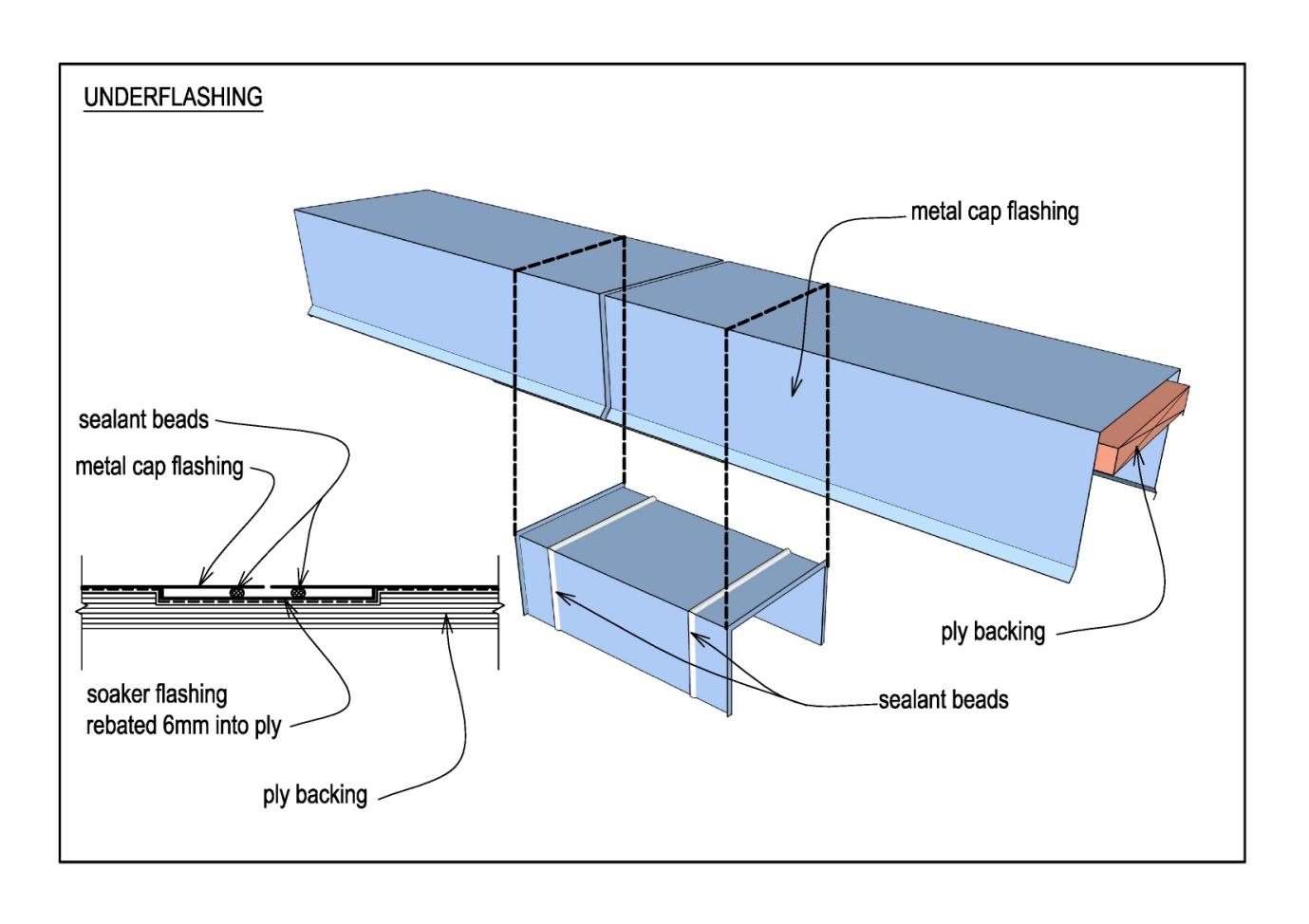
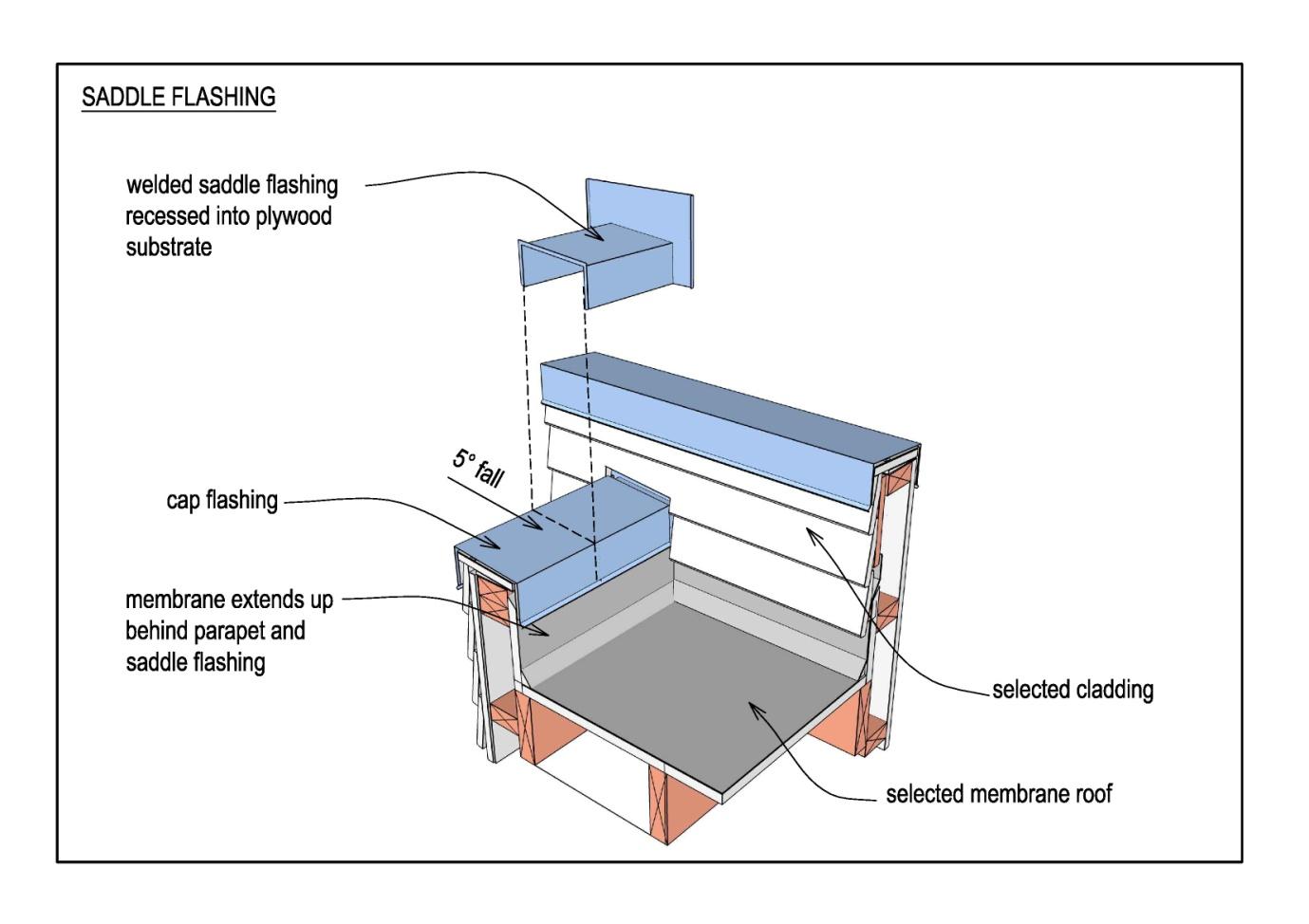
7.4
Parapets
Parapets provide a high risk of weather-tightness failure.
Parapets are a Restricted design element .
Released
Where parapets are provided:
cap-flashing shall be:
o metal
o fully supported with 5º minimum cross-fall
Weather-tightness and Durability Requirements – August 2014
29 | P a g e

o secured with side fixings or concealed clips (no top fixing)
joins and junctions shall be under-flashed with welded 1.6mm aluminium flashings,
rebated into plywood substrate
there shall be no reliance on sealant alone for weatherproofing.
Refer to the following sketches for typical details.
(1982)
Act
Information
Official
the
under
Released
Weather-tightness and Durability Requirements – August 2014
30 | P a g e
(1982)
Act
Information
Official
the
under
Released
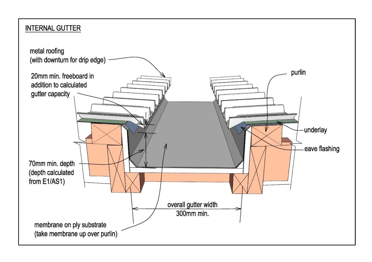
7.5
Internal gutters
Significant damage can result when an internal gutter fails.
Weather-tightness and Durability Requirements – August 2014
31 | P a g e
 Internal gutters are a Restricted design element .
Projects which incorporate internal gutters require precise detailing and an increased level of
attendance and observation by the Designer at the time the substrate is fitted and the gutter
lining installed.
Where internal gutters occur:
welded stainless steel is the preferred gutter lining
membrane gutter linings shall be one continuous length (ie without joints)
fall shall be 1:100 minimum (preferably more, depending on depth)
levels of the high and low points of the substrate shall be shown on the drawings.
7.5.1 Gutter Capacity
The gutter:
design shall meet the requirements of NZBC Clause E1 – Surface Water
(1982)
capacity shall accommodate twice the “1 in 50-year” rainfall intensity.
Local rainfall intensity shall be obtained from NIWA or the Territorial Authority.
Act
Suitable design methods are provided in E1 / AS1 and BRANZ Bulletin 537 Sizing
Gutters and Downpipes.
7.5.2 Gutter Outlets
Outlets from internal gutters shall penetrate the external wall to discharge into a
rainwater head:
full width of the gutter shall extend through the wall into the rainwater head
gutter lining shall terminate with a drip-edge.
7.5.3 Gutter Overflows
Information
Overflows shall be provided as an opening within the rainwater head and
cross-sectional area of overflow shall be1.5 times the area required for the
outlet
height shall be set so that the overflow functions before water can enter the
structure, if the outlet or downpipe becomes blocked.
7.5.4 Testing
Official
Blocking the outlet and flood-testing to check the integrity of the gutter and operation
of the overflow, is recommended before roofing or internal linings are fitted.
the
under
Released
Weather-tightness and Durability Requirements – August 2014
32 | P a g e
(1982)
Act
Information
Official
the
7.6
Valley Gutters
Valley gutters shall not be fitted where the roof pitch is less than 80 (internal gutters
shall be constructed).
Refer to section 8.4.5 of NZ Metal Roof and Wall Cladding Code of Practice
Version 2.2 / 2012 for valley gutter design requirements.
under
Section 8
Exterior Joinery
Circular windows are not permitted .
The following window types are Restricted design elements .
complex shapes
raking or curved heads
Released
curtain wall glazing exceeding 2 storeys in height
recessed, other than provided for in E2/AS1 (sill flashings tend to accumulate water
rather than shield and drip away from opening between the window frame and sill
flashing).
Weather-tightness and Durability Requirements – August 2014
33 | P a g e
Windows shall comply with NZS 4211
Section 9
Balconies
The following design elements are not permitted with upper floor balconies :
construction using cantilevered timber joists
cantilevered glass balustrade without a handrail
Balconies constructed over occupied spaces are a Restricted design
Balconies to which students have access:
(1982)
shall be designed to discourage students from sitting on the balustrade
shall give special attention to safety-from-falling.
Solid Balustrades:
Act
shall be constructed with tops flashed and stopped as if a roof parapet.
Section 10
Junctions with Existing Buildings
Attaching new construction to an existing building, is a Restricted design element .
The junction between the envelope of a new building and that of an existing, provides a
potential source of water ingress, particularly when design requirements such as seismic
junctions are involved.
Information
Section 11
Exposed Structural Elements
Structural (or other) elements which penetrate the exterior rain-screen, are
Restricted design elements.
Official
Penetrations through the building envelope by structural elements (ie supporting roof
overhangs) are a potential source of water ingress.
the
Section 12
Durability
under
Materials are expected to maintain their durability over the life of the building and not
deteriorate from premature corrosion.
The following factors will affect the long term durability of materials:
proximity to salt-laden atmosphere
industrial atmospheric contaminants
ability of rain to reach and wash contaminants from the surface of metals
the characteristics of the material selected.
Eaves / overhangs are encouraged but they prevent rain reaching:
Released
their underside
wall surfaces immediately below them.
Weather-tightness and Durability Requirements – August 2014
34 | P a g e
Materials selected for walls under wide overhangs shall be selected / coated with this in
mind.
The underside of eaves up to 900 wide shall be lined.
The following elements shall be protected with an appropriate industrial paint system
(ensure that any Manufacturer’s warranty remains valid):
underside of exposed metal roofing on overhangs wider than 900mm
exposed structural elements that are not rain washed.
Painted or coloursteel flashings should be avoided in protected locations (ie not rain-washed).
The following details are Restricted design features.
metal cladding on walls under eaves wider than 900mm
exposed metal structural elements under eaves or overhangs.
overhangs wider than 900mm where the underside of metal roofing is
(1982)
exposed.
Act
Information
Official
the
under
Released
Weather-tightness and Durability Requirements – August 2014
35 | P a g e


Appendix A
To be completed by the Designer and submitted to the Project Manager at completion of
Detailed Design.
Weather-tightness / Durability Check Sheet
(1982)
SCHOOL NAME
………………..….………………………………..
SCHOOL I.D.
……………….……………………………………
Act
PROJECT NAME
…………………………………………………….
PROJECT I.D.
…………………………………………………….
PROGRAMME YEAR FUNDING ALLOCATED...…………………………….
FUNDING SOURCE LISTED IN PMIS.………………………………………….
I / we confirm that:
this project does not contain materials or features which are
Prohibited in the
Information
Weather-tight and Durability Requirements for Schools – June 2014 publication
this project does not contain materials or elements whose use is
Restricted
this project includes the following materials or features whose use is
Restricted and
full construction details for these items are appended
………………..….………………………………..
Official
……………….……………………………………
the
where applicable, features and elements have been designed in compliance with
details and clauses in the
Requirements
this project includes the following features or elements that have not been designed
in compliance with details or clauses in the
Requirements and full construction
details of these items are appended
under
………………..….………………………………..
……………….……………………………………
COMPANY
………………..….………………………………..
DESIGNER’S NAME
……………….……………………………………
DESIGNER’S SIGNATURE ………………..….………………………………..
Released
DATE ………………..….………………………………..
Weather-tightness and Durability Requirements – August 2014
36 | P a g e
Document Outline