
Signals New Zealand User G
Page 1
roup ( SNUG)
National Traffic Signals
Specification 2013 Rev01
Superseding the National Signals Specification 2005
Sign
als
Spe
ci
fication 2
013
link to page 5 link to page 6 link to page 6 link to page 6 link to page 7 link to page 7 link to page 7 link to page 8 link to page 8 link to page 8 link to page 8 link to page 8 link to page 9 link to page 9 link to page 9 link to page 10 link to page 10 link to page 10 link to page 11 link to page 11 link to page 11 link to page 11 link to page 11 link to page 11 link to page 11 link to page 11 link to page 12 link to page 13 link to page 13 link to page 13 link to page 13 link to page 14 link to page 14 link to page 14 link to page 14 link to page 14 link to page 14 link to page 14 link to page 14 link to page 15 link to page 15 link to page 15 link to page 15 link to page 16 link to page 16 link to page 16 link to page 16 link to page 16 link to page 16 link to page 16
Page 2
CONTENTS
DISCLAIMER .............................................................................................................................................................5
REVISION DETAILS ................................................................................................................................................6
ABBREVIATIONS .....................................................................................................................................................6
SPECIFICATIONS .....................................................................................................................................................6
Section 1 – GENERAL REQUIREMENTS ..............................................................................................................7
1.1
INTRODUCTION ..............................................................................................................................................7
1.2
SPECIFICATIONS / STANDARDS .......................................................................................................................7
Section 2 - minimum requirements of signal equipment .........................................................................................8
2.1
SCOPE ............................................................................................................................................................8
2.2
SIGNAL EQUIPMENT COMPLIANCE AND APPROVALS .....................................................................................8
2.2.1
Provisional Approval ............................................................................................................................8
2.2.2
Guarantee Period ..................................................................................................................................8
2.3
TRAFFIC SIGNAL CONTROLLER ......................................................................................................................9
2.3.1
AS2578:2009 - Traffic Signal Controller ..............................................................................................9
2.3.2
New Zealand Special Conditions to AS2578:2009 ................................................................................9
2.3.3
Controller Firmware ........................................................................................................................... 10
2.3.4
SCATS Compliance and TRAFF Version ............................................................................................ 10
2.3.5
New Controller Types.......................................................................................................................... 10
2.4
SIGNAL LANTERNS ....................................................................................................................................... 11
2.4.1
General ................................................................................................................................................ 11
2.4.2
Signal Sizes ......................................................................................................................................... 11
2.4.3
LED Lanterns ...................................................................................................................................... 11
2.4.4
Lantern Body Construction ................................................................................................................. 11
Visors (Cowls) ............................................................................................................................................. 11
2.4.5 .................................................................................................................................................................... 11
2.4.6
Target Boards (Backing Boards) ........................................................................................................ 11
2.5
POLES (POSTS) AND POLE TERMINAL ASSEMBLIES ...................................................................................... 12
2.5.1
Pole Terminal Assemblies ................................................................................................................... 13
2.5.1.1
Switch Terminations (Terminal Assemblies) .................................................................................................. 13
2.5.1.2
Neutral Terminations ....................................................................................................................................... 13
2.5.1.3
Earth Terminations .......................................................................................................................................... 13
2.5.1.4
5 meter Pole Termination (Terminal Assembly Unit) ..................................................................................... 14
2.5.1.5
Mastarm Pole Termination .............................................................................................................................. 14
2.6
PEDESTRIAN AND CYCLE DETECTION .......................................................................................................... 14
Pedestrian Push Button Assemblies ............................................................................................................ 14
2.6.1 .................................................................................................................................................................... 14
In Ground (IGD) or Above Ground (AGD) ................................................................................................. 14
2.6.2
Pedestrian Detection ........................................................................................................................... 14
2.6.2.1
In Ground Pedestrian Detection (IGD) ............................................................................................................ 14
2.6.2.2
Above Ground Pedestrian Detection (AGD) ................................................................................................... 15
2.6.3
Cycle Push Button Assemblies ............................................................................................................ 15
2.7
INDUCTIVE LOOP DETECTORS (VEHICLE AND CYCLE) ................................................................................. 15
2.8
TESTING OF EQUIPMENT .............................................................................................................................. 15
Section 3 - INSTALLATION AND COMMISSIONING OF TRAFFIC SIGNAL EQUIPMENT.................... 16
3.1
SCOPE .......................................................................................................................................................... 16
3.2
TEMPORARY TRAFFIC MANAGEMENT .......................................................................................................... 16
3.3
SUPPLY OF ELECTRIC POWER ....................................................................................................................... 16
3.4
WATERPROOFING ......................................................................................................................................... 16
3.5
ELECTRICAL WIRING ................................................................................................................................... 16
3.5.1
Pole Top Cable Terminations ............................................................................................................. 16
link to page 17 link to page 17 link to page 17 link to page 17 link to page 18 link to page 18 link to page 18 link to page 18 link to page 19 link to page 19 link to page 20 link to page 20 link to page 21 link to page 21 link to page 21 link to page 22 link to page 22 link to page 23 link to page 23 link to page 24 link to page 24 link to page 24 link to page 26 link to page 26 link to page 26 link to page 26 link to page 26 link to page 26 link to page 26 link to page 27 link to page 27 link to page 27 link to page 27 link to page 29 link to page 29 link to page 29 link to page 29 link to page 29 link to page 30 link to page 30 link to page 30 link to page 31
Page 3
3.5.2
Earthing (Bonding) ............................................................................................................................. 17
3.5.3
Cable Termination Chart .................................................................................................................... 17
3.6
CONTROLLER CABINET ................................................................................................................................ 17
3.7
CONTROLLER TERMINATIONS ...................................................................................................................... 17
3.8
EXTERNAL VEHICLE LOOP DETECTOR UNITS .............................................................................................. 18
3.9
POLE (POST) LOCATIONS AND INSTALLATION ............................................................................................. 18
3.10
SIGNAL LANTERNS ....................................................................................................................................... 18
3.10.1
Lantern Mounting Supports and Straps .............................................................................................. 18
3.10.2
Lantern Leads...................................................................................................................................... 19
3.10.3
Siting of Signal Lanterns ..................................................................................................................... 19
3.10.4
Covering of Lanterns ........................................................................................................................... 20
3.11
INDUCTIVE LOOPS ........................................................................................................................................ 20
3.11.1
Loop Feeder Connections ................................................................................................................... 21
3.12
PEDESTRIAN AND CYCLE PUSH BUTTON ASSEMBLY ................................................................................... 21
3.13
PAINTING / SURFACE COATING OF EQUIPMENT ............................................................................................ 21
3.14
SPECIAL TOOLS AND KEYS .......................................................................................................................... 22
3.15
ACCEPTANCE AND TESTING ......................................................................................................................... 22
3.15.2
Earthing and Earth Impedance Test ................................................................................................... 23
3.15.3
Software (Personality) Controller Bench Test .................................................................................... 23
3.15.4
Commissioning .................................................................................................................................... 24
3.16
AS BUILT DOCUMENTATION TO BE PROVIDED ............................................................................................. 24
3.17
PROCEDURE FOR TURNING OFF SIGNALS ..................................................................................................... 24
Section 4 - CABLING AND CIVIL WORKS ......................................................................................................... 26
4.1
SCOPE .......................................................................................................................................................... 26
4.2
CABLE DIAGRAM ......................................................................................................................................... 26
4.3
TRENCHING .................................................................................................................................................. 26
4.4
CABLING, DUCTING AND SIGNAL DUCT ACCESS CHAMBERS....................................................................... 26
4.4.1
Ducting ................................................................................................................................................ 26
4.4.1.1
Pole Access Ducting ........................................................................................................................................ 26
4.4.2
Signal Duct Access Chambers ............................................................................................................. 27
4.4.3
Power Cable ........................................................................................................................................ 27
4.4.3.1
Amendments to AS/NZS 2276.1 ..................................................................................................................... 27
4.4.4
Loop Feeder Cable .............................................................................................................................. 27
4.4.5
Mains Power Supply............................................................................................................................ 29
Earthing ...................................................................................................................................................... 29
4.4.6 .................................................................................................................................................................... 29
4.5
INSTALLATION OF SIGNAL POLES AND MASTARM / JUMA / JUSP POLES ................................................... 29
4.6
CONTROLLER BASE ...................................................................................................................................... 29
4.7
KERB SIDE JUNCTION BOXES (KJB‟S) ......................................................................................................... 30
4.8
LABELLING OF CABLES ................................................................................................................................ 30
4.9
CABLING DOCUMENTATION ......................................................................................................................... 30
Section 5 - MAINTENANCE OF NEW WORK .................................................................................................... 31
APPENDICES
Appendix A
Signal Pole Details
Appendix B
5 meter Pole Top Assembly Details
Appendix C
Inductive Loop Layout Details
Appendix D
Pole Duct Access Details
Appendix E
Lantern Shroud Details
Appendix F
Cable Termination Chart
Appendix G
Site Acceptance Test Chart
Appendix H
Controller Bench Testing Form
Appendix I
New Intersection Commissioning Form
Appendix J
RAMM Asset Data Form
Appendix K
Controller Gland Plate and Removable Access Panel
Page 4
Page 5
DISCLAIMER
This specification has been produced by members of the National Signals Committee and the Signals New Zealand User
Group (SNUG) and includes input from representatives of the traffic signal industry.
It is the combination of several specifications from the larger cities and brings together the best practice and procedures
currently in use throughout the country. Users of this specification must ascertain for themselves that it represents the
requirements of their clients or Road Controlling Authority (RCA).
Page 6
REVISION DETAILS
Revision No.
Date
Section
Description
ABBREVIATIONS
Abbreviation
Description
AGD
Above Ground Pedestrian protection
CIS
Controller Information Sheet
DLP
Defects Liability Period
IGD
In Ground Pedestrian detection
JUMA
Joint use Signal Mastarm and Streetlight Pole
JUSP
Joint Use Signal and Streetlight Pole
KJB
Kerbside Junction Box
LED
Light Emitting Diode
MPa
Megapascals
NZTA
New Zealand Transport Authority
UMB
Upper Mounting Bracket
RCA
Road Controlling Authority
SCATS
Sydney Coordinated Adaptive Traffic System
SNUG
Signals New Zealand User Group
TMP
Traffic Management Plan
SPECIFICATIONS
No.
Description
AS/NZS 3000
Electrical Wiring regulations
AS/NZS 2144
Traffic Signal Lanterns
AS 1163
??
AS/NZS 4792
Galvanising ???
AS 2352
Pedestrian Push Button Assemblies
NZS 3910
Conditions of Contract for Building and Civil Engineering Construction
AS/NZS 2276.3
Cables For Traffic Signal Installations, Part 3 - Loop Cable for Vehicle Detectors
AS/NZS 2276.1
Cables for Traffic Signal Installations, Part 1 – Multicore Power Cables
NZECP 34
New Zealand Code of Practice for Electrical Safe Distances
NZS 3109
Concrete Construction
AS/NZS 4058
Precast Concrete Pipes
NZS 3144
Specification for Concrete Surface Finishes
AS 3996
Access covers and grates
Page 7
Section 1 – GENERAL REQUIREMENTS
1.1 Introduction
Whilst this specification is intended to encompass the best practice for the supply and installation of traffic
signals throughout the country it is recognised that individual Road Controlling Authorities (RCA‟s) will have
their own specific requirements. Therefore this specification needs to be read in conjunction with the
Regional Special Conditions to the National Signals Specification as produced by the local RCA in which the
work is being undertaken.
1.2 Specifications / Standards
All cable, equipment and installation shall satisfy the requirements of the Electrical Wiring Regulations
AS/NZS 3000 (and any amendments) and the Local Power Supply Authority.
Any communication equipment likely to be connected to the Telecom network shall be Telecom approved.
All Standards referenced in this specification maybe superseded by a revised version. Where a standard
has been superseded the Standard referenced in this Specification shall be replaced most recent version of
the Standard.
Page 8
Section 2 - MINIMUM REQUIREMENTS OF SIGNAL EQUIPMENT
2.1
Scope
This Section of the Specification covers the requirements of all signal equipment offered for supply and
installation, including the local signal controller, controller cabinet, detectors, lanterns, target boards, visors,
poles and pole top assemblies and push button assemblies.
2.2
Signal Equipment Compliance and Approvals
All traffic signal components must comply with this specification and must either:
(a)
Have been previously supplied to the Road Controlling Authority (RCA) / Client and found
satisfactory in operation, or
(b)
Be demonstrated in a working condition to the RCA / Clients Engineer before the closing date for
tenders. The Engineer may give provisional approval if, in his opinion, the equipment is fit for purpose and is
able to be connected to the SCATS Traffic Management System (if required to be connected to SCATS). –
Refer Section 2.2.1 Provisional Approval
The equipment shall also comply with all relevant electrical regulations and local Power Supply Authorities
requirements.
2.2.1
Provisional Approval
Provisional approval for non-complying equipment may be given by the RCA / Client providing it can be
shown that the proposed equipment meets all specified requirements, including safety and other regulatory
requirements, and provides the same desired outcome.
Equipment with provisional type approval will be required to operate in accordance with this Specification and
will not remove the Contractors obligations under Section‟s 4 and 5 regarding maintenance. In many cases,
equipment with provisional type approval may require maintaining for a longer period than one year. The
Contractor will be notified of this period when granted provisional type approval. Maintenance, at no cost to
the RCA / Client, will be required until full approval for the equipment is given.
In general, equipment will be required to operate under normal working conditions without failure for a period
of 12 months. This may apply to one-off or a multiple number of units.
2.2.2
Guarantee Period
Unless specified elsewhere in this document, all equipment / hardware supplied or installed shall be guaranteed
against faulty materials and workmanship for a period of one year from the date of commissioning. (Note: The
Guarantee period commences from the date of commissioning and not the date of manufacture).
Where there is a difference between the main contracts Defects and Liability requirements and this
specification the longer time period shall apply.
Some exceptions to the above are traffic signal controller components, poles and painting.
LED (Lamp) module shall have a five year guarantee period. In terms of new installations the guarantee period
shall commence from the date of commissioning. For replacement modules the guarantee period shall
commence from the date of installation of the LED (Lamp) module.
For new installations, commissioning of the signals shall be deemed to have occurred on the date when the
installation has passed all of the pre-commissioning tests and the RCA‟s Engineer has signed the Site
Acceptance (or similar) form.
Page 9
Refer Section 5.1 for procedure for cost recovery for any failure or fault during the contract Maintenance or
Defects Liability Period.
2.3
Traffic Signal Controller
2.3.1
AS2578:2009 - Traffic Signal Controller
Subject to the following special conditions, the Traffic Signals Controller must comply with AS2578:2009.
This includes all aspects of the controller, cabling, mounting, cabinet, and logic rack as detailed in
AS2578:2009, including the provision of options as detailed in AS2578:2009 Appendix A.
2.3.2
New Zealand Special Conditions to AS2578:2009
The following amendments shall be made to AS2578:2009 for supply and installation in New Zealand. The
numbers referred to are the item numbers in AS2578:2009.
AS2578:2009 Requirement 1.4.10 – Additional requirement for New Zealand
In accordance with AS/NZS3000, the RCD supplied must meet the conditions of AS/NZS3000:2007 2.6.2.2
for
New Zealand installations.
AS2578:2009 Requirement 2.3.3 – Additional Requirement for New Zealand
The controller must have ventilation grilles in the base, above the finished ground level, and below the gland
plate as detailed in Section 2.3.4. A recommended option is to fit a „pedestal‟ between the base and the
controller cabinet. This pedestal must be at least 100mm tall, and the same width and depth as the controller
cabinet and base.
AS2578:2009 Requirement 2.3.4 – Additional requirement for New Zealand
A gland plate and removable access panel shall be fitted at the bottom of the controller cabinet. A suitable
example is shown in Appendix K. Any unused cable entries must be „plugged‟ with plugs that can be easily
removed. The glands, gland plate and access panel must be capable of preventing entry for vermin etc into the
bottom of the controller cabinet.
The access panel must be installed to allow easy removal for maintenance tasks in the bottom of the cabinet.
AS2578:2009 Requirement 2.3.7 – For New Zealand remove figure 2.5.
AS2578:2009 Requirement 2.3.7 - Additional requirement for New Zealand as per NOTE.
The purchaser requirement for New Zealand cabinet locking is as follows –
1.
Recessed Handle(s),
2.
Three-point locking at top, bottom, & side,
3.
A single-key mechanism, with the lock as specified by the RCA in their “Regional Special Conditions
to the National Signals Specification”.
AS2578:2009 Requirement 2.3.12 – Change requirement for New Zealand
Replace second paragraph with –
The equipment shelf shall be mounted not less than 390mm below the top of the door opening, and this shelf
shall be the width of the controller cabinet.
AS2578:2009 Requirement 2.3.12 – Additional requirement for New Zealand
The equipment shelf must be sufficiently deep enough to hold the logic module, but must have at least 50mm
clearance from the front face to the inside of the door.
New requirement to AS2578:2009 for New Zealand
2.5.12 Communications Socket Outlet and MCB
A circuit breaker shall be installed in the „spare position‟ as provided for in 2.5.11.(f). This circuit breaker
shall be rated at 16 A, Type C, with a fault-make load-break fault current rating not less than 8 kA, and shall
control a new double-socket outlet specifically for communications and camera equipment, where the 230v
power for such equipment is supplied by 3-pin plug. The communications equipment socket outlet must be
Page 10
clearly labelled “Communications Equipment Only – NOT RCD PROTECTED”. RCD protection must not be
provided for this socket.
New Requirement to AS2578:2009 for New Zealand
2.5.13 Street Lighting Power
Where there is a power supply to street-lighting fed through the traffic signals cabinet, it shall be installed as
per the local RCA‟s “Regional Special Conditions to the National Signals Specification”. This street lighting
circuit must be supplied through the traffic signal controller mains power isolation switch.
*Note - the „Detector‟ MCB detailed in 2.5.11 (d) may be re-tasked as the street-lighting circuit protection.
New Requirement to AS2578:2009 for New Zealand
2.5.14 Electricity Revenue Meter
Each electrical retailer, and each electricity lines company have slight variations with their electricity revenue
meter requirements. For regional specifics, consult the local RCA‟s “Regional Special Conditions to the
National Signals Specification”.
AS2578:2009 Requirement 2.13.1 - Change requirement for New Zealand
Replace the entire paragraph with -
2.13.1 Conformance with New Zealand Communication Requirements
(a) Telepermit Requirements - Any device to be directly connected to the Chorus network must display the
New Zealand Telepermit label. For more information vis
it http://www.telepermit.co.nz. (b) Radio Requirements - Any wireless device must comply with the New Zealand Radio Communications
Act 1989. For more information vis
it http://www.rsm.govt.nz
AS2578:2009 Requirement 2.18 – NOTE
The service light is a standard requirement for all New Zealand controllers.
AS2578:2009 Requirement 2.22.5(b) – change requirement for New Zealand
Replace entire requirement with “Telepermit label and PTC number”
2.3.3
Controller Firmware
Prior to testing and installation, the following requirements must be met -
1. The controller must be designed in accordance with RMS TSC4 specification,
2. The controller (including logic rack and all other modules) must have the current manufacturer
software, firmware and hardware updates applied.
2.3.4
SCATS Compliance and TRAFF Version
Where the controller is to be connected to SCATS, the following conditions apply –
1. The controller must be running the latest version of TRAFF software, as notified by Roads & Maritime
Services (RMS),
2. A copy of the RMS SCATS Compatibility Certificate for that model of controller must be supplied to
the Engineer (if not already previously supplied).
2.3.5
New Controller Types
Where a contractor proposes to install a new controller type not previously installed in the area of the RCA,
the following conditions must be met –
1. Written approval must be obtained from the Engineer,
2. The supplier (or their agent) must offer to make a presentation on the controller to the Engineer, and
provide a loan logic rack at no charge to allow the Engineer to test the controller and become familiar
with it,
3. The supplier (or their agent) must provide a training course to the RCA‟s existing Maintenance
Contractor, at no charge to the Engineer or the Maintenance Contractor,
4. If the new controller requires special configuration tools, or will not work with the RCA‟s
Maintenance Contractors HHT, the supplier (or their agent) must provide all equipment required to
allow full HHT operation with the controller. This can include computer software, or a new HHT, as
required to integrate with the operations of the current Maintenance Contractor,
Page 11
5. The engineer has the final right to deny installation of any controller type in their area.
2.4
Signal Lanterns
2.4.1
General
The technical requirements for Traffic Signal Lanterns including cowls, visors and louvres shall be as stipulated
in AS/NZS 2144:2002 (Including amendments as issued from time to time), with the exception that all new
traffic signal lanterns shall be supplied with LED lamps.
2.4.2
Signal Sizes
The nominal size of pedestrian and general-purpose signals as referred to in clause 3.3 of AS/NZS 2144:2002
shall be 200 mm.
The nominal size of extended range signals as referred to in clause 3.3 of AS/NZS 2144:2002 shall be 300 mm.
(Note: Extended range signals shall be used on all overhead mastarm displays and on high speed approaches).
2.4.3
LED Lanterns
All LED lanterns, visors, louvers and target boards
must have an independent NATA certified laboratory report
confirming compliance with AS/NZS 2144:2002
2.4.4
Lantern Body Construction
Lantern bodies shall be constructed from aluminium or polycarbonate and be installed to the manufacturers‟
installation instructions.
The lantern doors shall be capable of being hinged on both the left and right without the need for tools. Lantern
doors shall be able to be replaced without the need to disturb the lantern mountings.
2.4.5
Visors (Cowls)
Each visor shall fit tightly against the door and shall not permit any perceptible filtration of light between the
door and the visor.
All Visors
shall be made from plastic.
Unless specified elsewhere all visors shall be one of the following:
(a)
Open Type Visor: For use on primary lanterns.
(b)
Closed Type Visor: For use on secondary or tertiary lanterns.
(c)
Pedestrian Visor: Each standard 200mm diameter pedestrian lantern shall be fitted with an approved
rectangular visor.
2.4.6
Target Boards (Backing Boards)
Target boards shall be fitted to each vehicle lantern supplied. The size of target boards shall be as specified in
AS/NZS 2144: 2002 and shall be constructed using type 5005 aluminium alloy with a minimum thickness of
1.6 mm. Each target board shall be fully interchangeable in accordance with the criteria recommended in
Appendix F of AS/NZS 2144: 2002. The surface treatment shall be baked enamel (black).
Page 12
Target Boards for 200 mm lanterns shall incorporate a 20 mm white painted border around the outside as set
out in Clause 7.9 of AS/NZS 2144: 2002.
Target Boards for 300 mm lanterns shall incorporate a 35 mm white baked enamel border.
2.5
Poles (Posts) and Pole Terminal Assemblies
The design requirements for all traffic poles shall be in accordance with the joint Australia/New Zealand
Standard AS/NZS 4676:2000 Structural Design Requirements for Utility Service Poles and AS/NZS 4677:2010
Steel Utility Service Poles.
Design of the components for strength will be in accordance with the parameters set out below.
Only standard poles and arms in accordance with the drawings in appendix are to be manufactured.
All traffic style poles, including mast arm poles (curved or mitred), standard traffic signal and hinged traffic
signal poles, JUMA, JUSP, ground planted, flange based or flange based stub shall be designed in accordance
with AS/NZS1170.2.2002 parts 0 and 1 and include a 10 year structural guarantee. Additionally, the following
specific design parameters are to be included:
Design Working Life
- 50 years
Importance Level
- 2
Wind Region
- Use code for region where traffic signals are to be installed
Terrain/Height Multiplier
- 2
Shielding Multiplier
- 1
Hill Shape Multiplier
- 1
Lee Zone Multiplier
- 1 (to a maximum of 1.35)
All JUSP, JUMA and Mast Arm Poles with curved outreach arms shall have a 10 degree tilt. In addition, poles
and arms shall comply with all dimensions shown in the drawings min Appendix A. The minimum spigot
diameter on JUSP and JUMA poles shall be 42mm o.d. In the case of the JUMA and JUSP poles, the street
lighting luminaire fitted to the outreach arm shall not exceed 0.15m² in sail area and have a mass of no more
than 15.0 kg. The tilt angle is detailed on the drawings.
All fixtures and fittings are detailed (traffic signals, pedestrian signals, street lights, signage and any other
fittings or fixtures required for the specific installation) along with the height at which their weight and windage
is to be calculated as a minimum. Drag coefficients are to be in accordance with table E4 of AS/NZS
4676:2000.
The JUSP pole door cavity/fuse opening shall be of a suitable weatherproof design and shall be positioned to
permit safe access for maintenance i.e. not facing the street/traffic lane. The ideal position would be to allow
the technician to view on-coming traffic. The cover plate shall be secured by a minimum of two child and
vandal resistant 304 grade stainless steel fasteners and will require a specialised tool to remove the fasteners for
maintenance.
In the case of octagonal JUSP poles, the door cavity/fuse opening shall be a standard size of 300mm x 140mm
and be positioned 600mm (to the base of the opening) above the finished ground level. In the case of the JUMA
pole, the door cavity/fuse opening for the street light isolation shall be a standard size of 180mm x 80mm and
be
positioned
just
below
the
mounting
flange
for
the
street
light
outreach
arm.
All steel tube used for manufacture of the 5.1 metre traffic light poles shall be a minimum of 100nb CHS to
C250LO in accordance with AS/NZS1163:2009.
Page 13
Pole strengths are based on AS/NZS 3404:2009 Steel Structures Standard. Steel sections strength requirements
apply to the base of the pole at the top of the concrete footing.
All welding shall be carried out in accordance with AS/NZS 1554.1:2004 Structural Steel Welding Part 1 and
welders must be qualified to AS/NZS 2980:2007. Inspections certificates by a duly qualified independent
inspection company are to be supplied for each batch manufactured.
Poles will be permanently marked (prior to painting) by way of indentation stamp to indicate date of
manufacture (dd/mm/yyyy) and the name of the manufacturer. This indentation stamp shall be located
immediately under the lower pedestrian mounting lug. Arms are to be identified in the same manner with the
location being on the outer surface, immediately above where the arm connects to the pole. The indentation
stamp letter and number size is to be of a size suitable to be easily identified. Lettering shall have a minimum
height of 7mm and a maximum height of 14mm. All marking is to be applied prior to painting.
All JUMA, JUSP and Mast Arm Poles and arms shall be finished, both internally and externally in accordance
with AS/NZS4680:2006, Hot Dip Galvanising Standard. Ready galvanised steel, spray on galvanising or
thermal zinc will not be accepted. In addition, pole coatings shall be in accordance with AS/NZS 2312:2002
with certification to Category 'D' for a 10 year warranty to first maintenance.
Each pole type will require a PS1 certificate to be issued by suitably qualified CPENZ Registered Engineer.
This certificate shall include the specific design details for both the pole and when requested, the foundation
details and will be supplied at time of tender.
Mounting of the poles are of two possible types - ground planted and concrete pad.
Ground planted poles are an extension of the pole below the finished ground surface. The length below ground
will vary depending on the model of pole being installed and ground conditions in the location. The minimum
soil bearing capacity should be 100kPa. If any less than this, a site specific foundation design will be required.
Concrete pad mounted poles will typically be of a flange based type. These poles will require a concrete pad or
pile to be constructed that will include during casting of a suitable holding down bolt cage. Pads and piles are
typically used in locations where the ground conditions aren't stable enough to maintain overturning resistance.
2.5.1
Pole Terminal Assemblies
2.5.1.1 Switch Terminations (Terminal Assemblies)
2
The terminal assembly shall consist of sufficient 2.5 mm
2-in-2-out knife edge disconnect
terminals for the number of cores to be terminated. The terminals shall spring loaded screw locked
incorporating a screw and spring-tensioned system or have a minimum of one screw per cable core. The
neutral and earth terminals shall be double through terminals to facilitate a greater number of
terminations. The terminals shall be mounted on aluminium rails and end clamps shall be provided at
each end of the rail. Each terminal shall be clearly labelled.
2.5.1.2 Neutral Terminations
The terminals shall meet the requirements of Clause 2.5.1.1 excepting that they shall not use switch
terminations.
2.5.1.3 Earth Terminations
The earth bus bar shall provide ten outputs with connectable cross-sections measuring 10 mm2 and 16 mm2
configured alternately. The bar shall be rail mounted and have a rated voltage of 450V and be rated IP20. The
insulating material shall meet the reference standard IEC 60998-1 and IEC 60998-2-1.
Page 14
2.5.1.4 5 meter Pole Termination (Terminal Assembly Unit)
The top of each standard 5m pole shall be fitted with a terminal assembly unit and cover meeting the
requirements as shown in Appendix B.
The pole top and full upper mounting bracket (UMB) must be a combined unit complete with cable
terminal and lantern lead supports, and a final cap capable of being fastened into position so that it cannot
be removed if the securing bolts are loose.
The finial cap must be made of plastic and constructed to fit snugly over the pole top to minimise the
ingress of dirt and grime. The finial cap shall be secured to the UMB by a wire lanyard to prevent it
from blowing away if not fastened correctly. Metal finial caps will not be acceptable.
All nuts, washers, bolts and fasteners shall be galvanised, and the pole top/mounting bracket shall be
constructed in a non-corrosive material.
2.5.1.5 Mastarm Pole Termination
All mastarm poles shall have a terminal assembly box (Montrose box) mounted no lower than 3.5 meters
from the adjacent ground level.
The box shall be c o n s t r u c t e d f r o m aluminium or polycarbonate with m i n i m u m d i me n s i o n s o f
400 x 350 x 120mm rated to lP 65. It shall be bolted to the pole a n d s h a l l i n c l u d e a rubber seal or
gland between the box and the pole metalwork to create a waterproof seal. The Lantern leads shall enter
through the underside of the box. Any cables entering through the back of the box shall be held by a
compression gland. No holes will be permitted in the box that will allow condensation or moisture to
enter.
All cables shall be terminated in accordance with the details shown on the Cable Termination Chart (Refer
Appendix F for example).
2.6
Pedestrian and Cycle Detection
2.6.1
Pedestrian Push Button Assemblies
Pedestrian push-button assemblies shall contain audio and tactile facilities and shall comply with AS 2353-1999
“Pedestrian Push Button Assemblies”.
In addition the following requirements shall be met:
(i)
The call box shall provide an audible locating and “WALK” signal.
(ii)
The push button assembly shall incorporate an ambient noise control device .
(iii)
The tactile function must be continually operational; however the audio signal should be able to be
muted.
2.6.2
In Ground (IGD) or Above Ground (AGD)
Pedestrian Detection
All IGD /AGD detection and related equipment must have prior approval from the Engineer.
2.6.2.1
In Ground Pedestrian Detection (IGD)
All IGD units shall comply with the layout and form as described in “RTS 14 – Guidelines for Installing
Pedestrian Facilities for People with Vision Impairment” and the Pedestrian Planning and Design Guide
produced by NZTA.
Page 15
The detection output must be compatible with the standard inductive loop detector unit technology.
They shall be made from colour fast material and be capable of withstanding vehicle loadings.
2.6.2.2
Above Ground Pedestrian Detection (AGD)
All AGD units must be located such that they are able to cover the required area of detection and must be
compatible with the traffic signal controller detection and operation.
2.6.3
Cycle Push Button Assemblies
Cycle push button assemblies shall be the same as the pedestrian push-button assemblies accept that:
(a)
They shall be coloured blue.
(b)
The audio and tactile facilities are not required.
(d)
The embossed arrow disc shall be replaced with a red lens similar to a vehicle signal lens and
embossed with the cycle symbol.
(e)
They shall incorporate a visual call accept signal.
2.7
Inductive Loop Detectors (Vehicle and Cycle)
Inductive loop detectors may be either preformed or saw cut on site.
Where preformed loops are to be installed they must have site specific approval of the Engineer. Each
preformed loop must be constructed to meet the dimensions and lane offsets as in the diagram in Appendix C
Where non inductive detection technology is to be used (e.g. camera technology) it must have site specific
approval of the Engineer.
2.8
Testing of Equipment
All signal equipment supplied and/or installed including the signal controller, load switching equipment, cable
terminals, plugs etc is to be fully tested under simulated working conditions before being installed on site.
For acceptance and testing during installation refer Section 3.15 – Acceptance and Testing
link to page 30
Page 16
Section 3 - INSTALLATION AND COMMISSIONING OF TRAFFIC SIGNAL EQUIPMENT
3.1
Scope
This Section of the Specification covers the installation and commissioning of signal equipment including the
controller, cabinet, vehicle and pedestrian signals, call boxes, detection equipment and detector loops. It also
covers the painting of equipment.
3.2
Temporary Traffic Management
The contractor shall be responsible for the supply and erection of all necessary barricades, warning notices,
lights, etc, as required under Section 5.7.2 of NZS 3910: 2003 Conditions of Contract for Building and Civil
Engineering Construction and as required by the Transit New Zealand Code of Practice for Temporary Traffic
Management or to any other specific documents that may be provided by the RCA / Client.
The contractor shall obtain from the RCA whatever approvals are required to be able to work on the roadway
under the RCA‟s control.
3.3
Supply of Electric Power
The contractor shall be responsible for arranging, with the Road Controlling Authority‟s power supply
company, for the provision of a power meter and the switching on of power to the signal control cabinet. The
contractor shall pay all costs (including fees) associated with this work and shall get all necessary permits and
shall provide the Certificate of Compliance to the Engineer on completion of the works.
3.4
Waterproofing
All equipment below ground level shall be constructed and treated to permit continuous operation without fault
due to immersion in ground water or other corrosive agents commonly encountered on or beneath roads.
3.5
Electrical Wiring
All electrical work shall be completed in accordance with the current AS/NZS 3000 standard.
3.5.1
Pole Top Cable Terminations
All cables shall be brought up the interior of the signal pole or mastarm and terminated on the specified
terminal assemblies. All cables shall be firmly supported at the point of termination in such a manner that the
weight of the cable shall not impose mechanical strain on the electrical connections.
The cores of each cable are consecutively numbered on the core insulation and each core shall be terminated
into the terminal labelled with the same number.
Where a 36 core cable is not used (generally in existing installations) and there is more than one cable coming
into a pole then the largest cored cable or cable labelled „A‟ (see Claus
e 4.8), shall start at terminal 1 with the
smaller cables following on. For example with a 25 plus a 12 core cable, core 1 of the 25 core will be
terminated into terminal 1 with core 1 of the 12 core terminating into terminal 26. It is not necessary to label
each core since core 6 say will always terminate into terminal 6.
The cable sheath shall be removed for an adequate length with due precautions being taken not to damage the
insulation of the individual cores. The cable cores shall be neatly formed and laced to allow individual
conductors to be connected to the appropriate numbered terminal in accordance with the approved Cable
Termination Chart (refer Appendix F for example). The cores of different cables shall not be laced together.
Page 17
The bunching and tying of cores shall be arranged such that all terminal labelling remains visible, and
individual cores may be conveniently disconnected from any terminal for subsequent maintenance. All cable
cores including spares shall be allocated terminals, and shall be terminated within the pole top.
3.5.2
Earthing (Bonding)
All metal components must be individually earthed in accordance with the AS/NZS 3000:2007 wiring
regulations, using a minimum size earthing cable of 4.0 mm2. Particular attention should be given to poles
(including mastarms), callboxes, finial caps, metal bodied signals, unused cable cores, controller and cabinet,
mastarm termination box and audio tactile driver box.
All unused cable cores shall be bonded to earth in the controller cabinet.
3.5.3
Cable Termination Chart
For all new installations, a cable termination chart (Refer Appendix F for example) shall be completed prior to
termination of cables onsite and supplied to the Engineer.
At existing sites the contractor shall amend the existing cable termination chart supplied by the Road
Controlling Authority. If no cable termination chart exists, the contractor shall be required to produce one
from existing cable documentation as appropriate.
All cabling both at the controller cabinet and at the pole must comply with the details of the cable termination
chart.
3.6
Controller Cabinet
The controller cabinet shall be securely fixed to a concrete foundation or preformed base with, at minimum,
four hot dipped galvanised bolts (minimum size M12) such that the cabinet is aligned true to the vertical and
cannot be rocked from side to side. Where a standard preformed base is not to be used the foundation details
must be supplied to the Engineer for approval.
Where the cabinet is not surrounded by concrete or asphalt a 300 mm wide concrete apron shall be provided
around the base of the controller. The apron shall be 100 mm thick and be widened to 600mm on the side
adjacent to the door. The apron shall be installed to provide drainage away from the controller to the adjacent
ground but to maintain a comfortable working platform.
3.7
Controller Terminations
All cables entering the controller cabinet shall be securely supported at their outer sheath to ensure that no
mechanical strain is transmitted to the electrical connections. The individual cores shall be neatly formed and
tied, and positioned such that access to housing terminals is not obstructed and terminal designations are not
obscured. Each cable shall be individually labelled in accordance with its designation as shown on the
approved cable termination chart.
All field wiring terminals in the controller cabinet shall be vertically mounted with sufficient terminals to cater
for the maximum number of signal group outputs within the Logic Rack. Each signal group (both pedestrian
and vehicle groups) shall be provided with three terminal groups. Each group shall consist of two 2 in-2 out
spring loaded screw locked terminals designed for 2.5mm2 cable.
Both terminals and signal groups shall be counted and labelled from the bottom up in the order: grp 1 green, grp
1 yellow, grp 1 red, grp 2 green, grp 2 yellow, grp 2 red etc. Group 1 to 4 shall be on the right-hand side.
Terminal separation plates shall be used between each signal group and end clamps shall be used at each end of
the rail.
An additional non-switched terminal unit shall be used and located on the left-hand side of the gear plate. This
unit shall include three terminal blocks for both earth and neutral, plus one separate terminal block for GP
Page 18
phase (wired through the GP circuit breaker), detector returns, pedestrian buttons, special inputs and outputs
etc.
The terminals shall be grouped together with the earth and neutral at the bottom, then any 230V supplies and
then the low voltage supplies at the top. A terminal separation plate shall be used between the earth and neutral
terminals and between the 230V and low voltage terminals.
Each terminal shall be clearly labelled with its function using labels supplied by the terminal manufacturer.
Where there is a schematic wiring diagram provided within the controller (generally on the inside of the
controller door) it shall provide a true representation of the physical on site wiring configuration.
3.8
External Vehicle Loop Detector Units
For all new signal installations the detector units shall be located in the controller cabinet.
In special cases, or where an existing installation is involved, detector equipment may have to be
accommodated in the weatherproof boxes attached to the signal pole nearest to the loop. Attachment of
detector units to poles on medians or small islands shall be avoided as far as practicable. Pole-mounted
detector units shall be mounted in an unobtrusive manner and such that convenient access can be obtained to it
from a ladder placed on the footpath.
The power supply for all detectors that are mounted external to the controller shall be taken from the output
side of the lamp isolation relay.
The connection of the loop feeder cable to the detector rack shall be carried out through terminals to allow easy
isolation of the loop/loop feeder side of the circuit for testing purposes. The terminals must be suitable for low
voltage and therefore standard disconnect terminals are not appropriate. The terminals should preferably be
mounted vertically down the left-hand side of the gear plate. The terminal rail shall be long enough to mount
sufficient terminals for 24 detectors.
The terminals shall be labelled with the on-street detector number.
The loop feeder shall be securely clamped with clamping bars to the gear plate so that no strain is placed on the
core conductor.
3.9
Pole (Post) Locations and Installation
All poles shall be sited in accordance with the approved design drawing with the appropriate clearances
Prior to installation the pole locations shall be marked on site and their locations approved by the Engineer.
Poles are to be positioned to ensure that no part of the signal lantern or backing board is closer than 300mm to
the face of the kerb.
Where not surrounded by concrete or asphalt the pole shall have a 500mm square 300mm deep 20Mpa concrete
surround. The concrete surround must be sufficient in width to ensure that the ducting finishes within the area
of the concrete in order to protect all cabling. (Refer Appendix D)
3.10
Signal Lanterns
3.10.1
Lantern Mounting Supports and Straps
All mounting hardware, bolts etc. must be hot dipped galvanised.
Pole top mounting assemblies or top mounting lugs must have a fixed mounting stud.
Each vehicle / pedestrian lantern group must be mounted individually.
Page 19
All signals attached to pole top assemblies must have their leads securely fixed to the assembly using clamping
bolts, nuts and washers or studs not less than 10 mm in diameter.
Each signal lantern shall be attached to its mounting brackets by galvanised steel mounting straps of sufficient
length to permit the lantern to be adjusted laterally to provide an adequate signal indication and vertically to
conform to the approach gradient. Straps shall comply with the table below:-
Strap Length
Strap Thickness
(mm)
Up to 150
3mm
151 to 250
5mm
251 to 400
6mm
Straps shall be in a continuous length without joints and one strap shall not be hung off another strap.
All nut and bolt assemblies shall be provided complete with locking washers.
3.10.2
Lantern Leads
The lantern leads shall:
(a)
Be covered with a continuous 15mm flexible hose from their exit point from the lantern to the
clamping point on the Upper Mounting Bracket.
(b)
The pole-connecting end of the hose shall be prepared so as to enable it to be firmly clamped in a
recess in the pole top assembly without undue distortion or crushing of the hose.
(c)
When hanging freely, the lantern lead shall extend down to approximately the halfway point of the
lantern.
3.10.3
Siting of Signal Lanterns
(a)
Siting and Alignment
Each lantern shall be sited and aligned in accordance with Austroads publications -
“Guide to Traffic
Engineering Management Part 10 – Traffic Control and Communication Devices”.
(b)
Lantern Mounting Height
Except where the tertiary or secondary lanterns are mounted within 10 metres of the vehicle limit line
all vehicle lanterns shall have a mounting height of 4.1 metres measured to the top mounting bracket of
lantern.
Where low level tertiary or secondary signal lanterns are located within 10 meters from the vehicle
stop line the mounting height shall be 3.1 meters to the top of mounting bracket the lantern.
The minimum clearance from ground level to the bottom of a target board for signals restricted by an
overhead obstruction is to be 2 meters.
The minimum clearance from the road surface to the bottom of the target board for overhead lanterns
is to be 5.3 meters. The maximum clearance is to be 5.8 meters.
Where the position of the signal poles as installed does not allow the recommended positioning or appropriate
visibility to be achieved, the contractor shall notify the Engineer before installing the lantern.
Page 20
3.10.4
Covering of Lanterns
Immediately following installation and during periods when the lanterns are not in use they must be covered to
completely obscure vision of lanterns at all times during installation.
The lanterns shall be covered using a shroud as detailed in Appendix E.
Where commissioning will take place within one day of lantern installation, the Engineer may allow a
dispensation from this clause but otherwise shrouding shall be necessary for the full period from installation
until commissioning.
3.11
Inductive Loops
Inductive loops shall be positioned so as to record the specified output from vehicles passing or occupying
the positions indicated on the appropriate plans and to the dimensions and locations shown in Appendix C.
The Contractor shall mark the required position of the inductive loop on the ground and inspect the road surface
to ensure that the site conditions, including seal conditions and roadway integrity, will in no way reduce the
operational performance of the detection equipment. If the contractor feels that the conditions are not
satisfactory they shall notify the Engineer before installing the detector loops. The contractor shall notify the
Engineer prior to closing the traffic lanes for the purpose of installing the loops so that the Engineer may attend
the site to carry out installation inspections as they consider appropriate.
The inductive loop wire shall consist of single core polypropylene insulated cable with a nominal cross-
sectional area of 1.5 mm2 complying with AS/NZS2276.3: -2002 “Cables For Traffic Signal Installations, Part
3 - Loop Cable for Vehicle Detectors”.
The cable shall be laid in one continuous un-jointed length, laying it twice around each loop as shown in
Appendix C. Tails for up to two loops can be laid in the same slot if required.
In general the detector loop wire shall be installed in a saw cut slot that is approximately 5 mm wide and 40 mm
deep to provide a minimum top cover to the wire of 12 mm. All saw cuts shall be straight and shall extend past
the loop corners to ensure the full depth of cut throughout. Prior to placing the loop wire, the slot shall be dried
and cleaned and free of debris to provide a smooth bed for the wire. The recommended method of doing this is
with compressed air.
When re-cutting loops, the new saw cut must be at least 300mm away from the old saw cut to minimise road
surface damage. If the saw cut for the loop tails is to go through the kerb, then it should go through an existing
mortar joint to minimise unsightly appearances.
The loop wire shall be “rolled” into the slot without damaging the insulation. This can be achieved using a thin
disc such as a modified saw blade but not a screwdriver. Special care shall be taken at the corners to ensure the
wire is curved rather than bent. Each loop shall be wired as shown in Appendix C.
Immediately following the installation of the loop wire, and prior to sealing, an insulation resistance test shall
be performed. The loop should have a resistance to earth of not less than 10 mega-ohms. Sealing shall be done
immediately following the loop insulation test has been completed.
The loop wire slot shall be sealed with Tixophlate or an approved equivalent flexible epoxy sealant, ensuring a
continuous seal over the complete length of the loop and loop tails. The sealant shall be finished flush to the
road surface.
Where the loop tail is cut through the kerb & channel the tails shall be inserted in a 5mm wide saw cut made
with a minimum 450mm diameter blade .The saw cut kerb and channel must be sealed with a sand cement
mortar.
Page 21
Loop Testing
All loops shall be tested by measuring the insulation to ground (earth) and the results recorded on the
commissioning sheet. The test shall be taken at 250v conductors to earth and a result of not less than 10M
(megohms) will be acceptable.
Saw cutting
The Contractor shall ensure that no solid matter enters any waterway as a result of the saw cutting operation.
This could require the placement of filters or similar on catchpits etc.
On completion of the installation the contractor shall ensure that the surrounding area is swept clean of all sand
and debris. This material shall be suitably disposed of.
Note: Due to noise and/or traffic flow conditions the RCA / Client may restrict the time at which detector loops
may be installed.
Preformed loops must be installed according to the manufacturers details and retain the correct shape and
dimensions as shown on Appendix C when installed.
3.11.1
Loop Feeder Connections
Where multi-pair feeder cable is used, the convention for terminating the loops shall be:-
(a) Pair 1 connected to the kerbside detector loop
(b) All remaining connections numbered consecutively from the kerb.
All unused pairs shall be sealed in a similar method to the loop connections.
The contractor shall make a clean, dry, waterproof electrical connection between the loop tails and the
loop feeder wires. The connection shall be located within a kerb side junction box. The feeder cable
sheathing must be sealed to ensure that no water may enter into the cable.
3.12
Pedestrian and Cycle Push Button Assembly
The push button assembly shall be mounted so that the underside of the assembly is 900 mm above the
pavement.
Unless specifically detailed, the pedestrian assembly shall be located in accordance with Section 5 of
RTS 14 –
Guidelines for Installing Pedestrian Facilities for People with Vision Impairment (i.e. the pedestrian assembly
shall be located so that the front of the assembly is perpendicular to the pedestrian crossing lines and so the
arrow disc will always be orientated so that the arrow is pointing straight up.
On non-staggered medians, the assembly shall be orientated parallel to pedestrian lines ensuring that the arrow
disc will be orientated so that the arrow is pointing parallel to the ground.
The cycle assembly shall be located so that the front of the assembly is parallel with the kerb. Note that wiring
for the call-accept is required for cycle call boxes.
3.13
Painting / Surface Coating of Equipment
All surface coatings shall carry a 10 year guarantee from their date of installation excepting where the
degradation is caused by vandalism.
The contractor shall supply the Engineer with the paint manufacturers documentation specifying their
maintenance requirements.
All painting of signal poles and equipment shall be as follows:
Page 22
(a) General
All new poles shall be pre coated prior to delivery on site
All coatings shall be applied in strict accordance with the manufacturer‟s recommendations.
No painting shall be carried out in wet, foggy, frosty, windy or dusty weather.
The colour yellow described in this specification shall be colour number 08E53 Golden Yellow as
described in BS 5252
(b) Painting Schedule
Standard Poles Gloss yellow to the pole top or as specified in the local RCA‟s amendments to this
Specification.
Overhead and Joint Use Poles
Unless modified in the local RCA‟s amendments to this Specification all overhead or
joint use poles shall be painted gloss yellow to the level of the top mounting bracket
supporting the low level vehicle lantern The remainder of the pole is to be left
unpainted.
.
Lanterns:
-
Signal face
gloss black
-
Signal housing
gloss black
-
Target boards
flat black
-
Signal visors
flat black internally
gloss black externally
Illuminated Signs
-
Sign face
gloss black
-
Sign housing
gloss black
-
Sign visors
flat black internally
gloss black externally
Pedestrian call boxes
gloss black
Cycle call boxes
gloss blue
Other Items (pole caps, detector
boxes etc)
yellow or as modified by the local RCA‟s
amendments to this Specification.
3.14
Special Tools and Keys
The Contractor shall supply to the Engineer one set of any special tools necessary to efficiently adjust and
operate the equipment. This equipment will not be required if previously supplied to the Road Controlling
Authority. The controller Key type will be as specified in the local RCA‟s amendments to this Specification..
3.15
Acceptance and Testing
On completion of the work, the equipment is to be left clean, free from dirt, dust, paint blemishes, etc. All
services, equipment and fittings shall be in proper working order and in good condition in accordance with this
Specification.
Pre Commissioning Tests
Page 23
When the Contractor has satisfied all of the requirements of the Power Supply Authority and considers that any
particular part of the Contract is ready for commissioning, the pre-commissioning checks as set out in the Site
Acceptance Sheet in Appendix G shall be performed in the presence of the Engineer or his representative.
The Contractor shall also provide an Electrical Certificate of Compliance to the Engineer prior to the pre-
commissioning check.
3.15.2
Earthing and Earth Impedance Test
The contractor to undertake an earth impendence test to AS/NZS3000:2007 (6.3.2 and 6.3.3) and submit results
in a report as part of their pre-commissioning checks. The tests shall include the following:
Earth resistance test-continuity of main earth conductor
Insulation resistance test for insulation
Earth resistance test for other earthed and equipotential bonded parts.
Consumer‟s main test – polarity and connections
Final sub-circuit test – polarity and connections
Earth fault loop impedance test
Verification of residual current devices (if fitted)
3.15.3
Software (Personality) Controller Bench Test
The contractor shall be required to confirm for themselves that the controller software (Personality) has been
programmed to operate in a safe manner and to the requirements of the Design Drawings and Controller
Information Sheet. If the contractor is of the opinion that the software is not operating correctly or safely, or
there are discrepancies between the design drawings and the CIS, then they shall immediately inform the
Engineer.
The Traffic Signal Contractor shall complete a FULL bench testing of the controller software (Personality) AT
LEAST ONE WEEK prior to the proposed commissioning date of the signal installation or intersection
upgrade.
All bench testing shall be based on the operation as specified in the latest revision of the Controller Information
Sheet (CIS), Signal Design Drawing and controller software (SFT) file.
The bench testing shall be undertaken using a similar controller operating under the same version of the
background (TRAFF) software as will be installed in the controller on site.
The bench testing shall include but not be limited to:
Confirmation that all detectors call and extend the relevant phases.
Confirmation that the correct signal displays / output groups are activated in the relevant phases.
Confirmation that each signal group output has been configured as either a Major, Minor or
Pedestrian output in accordance with the CIS.
Confirmation that all conflicting signal group outputs (both pedestrian and vehicle) cause the
controller to go into fault mode by physically inducing conflicting outputs. The Contractor shall
be required to confirm that the Conflict Matrix detailed in the CIS is correct and that the conflict
matrix programmed into the controller personality is the same as that shown in the CIS.
Confirmation that all time settings are consistent between the software and the CIS
Confirmation that the controller will operate under Flexilink mode of control
Confirmation that any Special Logic requirements work as specified
Confirmation that any Special Facility Flags (e.g. Z- , Z+ and any XSF bits) operate as specified
Page 24
The contractor installing the software shall submit completed and signed forms five working days prior to
commissioning the site verifying that the Traffic Signal Controller Personality has been FULLY bench tested.
A copy of the Controller Bench testing Form is included in Appendix H.
The contractor shall notify the Engineer at least 24 hours prior to the bench testing being undertaken so that the
Engineer may be present when the testing is being completed.
3.15.4
Commissioning
When the Engineer or his representative is satisfied that the signals are installed and operating in accordance
with the Specification, he will direct and supervise the commissioning of the signals.
The Contractor shall notify the Engineer 48 hour prior to commissioning the installation. Commissioning must
occur outside of the peak traffic periods at a time specified by the Engineer. No commissioning shall take place
on a Friday or the day before a public holiday.
Unless approved by the Engineer, commissioning will not be allowed until the controller has been installed on
site, and has had continuous SCATS communications for at least 48 hours.
An example of a commissioning check sheet for a new installation is included in Appendix I.
3.16
As Built Documentation to be provided
The contractor shall also supply in both electronic and hardcopy the following within 4 weeks of
commissioning -
a)
As built plan showing the final locations of all poles, access chambers, KJB, loops, lantern displays
and cabinets if they are different from the construction drawing.
b)
A completed Cable Termination Chart (in excel format). A Typical layout is shown in Appendix F.
c)
A completed Traffic Signal Asset Collection Form (Refer Appendix J) for RAMM .
d)
Results of all earth loop impedance testing carried out on all traffic signal poles and cabinets shall be
supplied to the RCA‟s Engineer prior to commissioning. The results shall be signed by the technician
who carried out the testing.
e)
A log book. The log book shall be completed every time the technician enters the cabinet and shall
detail the reason for entering the cabinet and a brief description of the work carried out. Each entry shall
be dated and signed.
f)
A copy of the electrical Certificate of Compliance.
At the time of commissioning a copy of Items a) and b) shall be provided within the controller cabinet along
with a log book and a copy of the Controller Information Sheet (CIS). Within 2 weeks of commissioning, a
laminated copy of a), b), and the CIS sheet must be inserted into the document pocket inside the controller
cabinet.
3.17
Procedure for Turning Off Signals
Where it is necessary to switch a controller either off or to flashing yellow or to take the site off-line or to
switch the signal displays off, notice must be given to the appropriate Road Controlling Authority. The RCA
staff must be notified immediately prior to such action being taken and immediately after the controller and
communications are fully operational again. The fact that the signals were turned off must be recorded in the
control cabinet log book.
When a signalised intersection is planned to be turned off or switched to flashing yellow for more than ten
minutes, the Contractor must ensure that the RCA‟s Engineer is informed so that arrangements for alternative
Page 25
control of the intersection can be made as they consider necessary. Once the Engineer has been notified, the
Contractor can proceed with turning off the signals unless specifically requested to wait for further assistance.
When a signalised intersection is
planned to be turned off (not flashing yellow) for more than ten minutes, the
Contractor shall adhere to an approved traffic management plan (TMP).
At no time during planned works shall an intersection be left unattended with the signals off unless an approved
TMP is in place. Also, at no time shall any warning signs or shrouds that indicate that the signals are not in
operation be in place on street when the signals
are working.
When there is an
unplanned outage of a signalised intersection (e.g. as the result of a controller fault or
accident), the Contractor must immediately assess the problem and where necessary make the site electrically
safe. If the signals can then be repaired and made operational (either fully or at least flashing yellow) within
one hour, and can be done so safely and without the need to work in a live lane, then the Contractor is to
proceed immediately with the repairs using a previously approved TMP that relates to the particular type and
location of the work. Refer to the Regional Special Conditions to the National Signal Specification if
operational repairs will take longer than one hour, or where work needs to occur within a live lane.
It should always be the intention of the Contractor to arrange the work so that the signals will be switched off or
set to flashing yellow for the shortest possible time. This will mean that wherever possible, work on the signals
is to be continuous until they are switched back to normal control. If a site is under approved temporary traffic
management (as set out in an approved traffic management plan), then it will normally be acceptable to turn the
signals back on with a reduced number of signal displays. Assuming good visibility of lanterns, the minimum
number of displays on any approach can be:
Primary or dual primary plus secondary, or
Primary or dual primary plus tertiary.
The intention to operate the signals with reduced displays must be highlighted in the TMP, which should detail
each approach where displays will be reduced. The Regional Special Conditions to the National Signal
Specification may set out additional RCA requirements.
Page 26
SECTION 4
Section 4 - CABLING AND CIVIL WORKS
4.1
Scope
This Section of the Specification covers the supply and installation of all cabling including multicore cable,
loop feeder cable, ducting, trenching and backfilling. It also covers the installation of kerbside junction boxes,
poles and controller base.
4.2
Cable Diagram
Cable sizes and approximate duct positions can be found on the schematic cable diagram on the Signal Drawing
but the Contractor should satisfy himself that the cabling and ducting shown is adequate for the signals
equipment depicted on the same drawing.
4.3
Trenching
All trenching and restoration work shall be in accordance with the Road Controlling Authority‟s specification.
Detailed traffic management plans must be approved before work commences.
Open cut trenching across carriageways shall only be carried out between the hours approved by the Engineer.
4.4
Cabling, Ducting and Signal Duct Access Chambers
4.4.1
Ducting
Ducting shall be installed from the controller to all signal duct access chambers, between chambers and from
the chamber to the signal pole in the locations indicated on the drawings.
The preferred method of installing the duct lines is by underground thrusting.
In open cut trenching, ducting for all multi-core cables shall use 100 mm diameter orange PVC Class D pipe
and shall be continuous between access chambers and from access chamber to
within 300mm of the base of
each pole. The ducts shall be placed no less than 600 mm and no more than 1000 mm below finished ground
level.
All thrusted ducting shall be continuous without any joints and must comply with the NZ Electrical regulations.
The minimum number of ducts from the controller and between access chambers is two (2).
All ducting is to be installed complete with draw wires to facilitate pulling through of cables. The draw wire
should remain in place on completion of cabling for future use and always replaced when used.
Ducting for loop feeder cables shall be a minimum 32 mm orange PVC Class D pipe laid to a depth of not less
than 300 mm and where provided directly behind the kerb. It shall be continuous between the Kerbside Junction
Box and the closest access chamber.
Where ducting pipes need to be joined they shall be jointed with an approved PVC cement.
Communications ducting should comply with the local RCA‟s requirements.
4.4.1.1 Pole Access Ducting
Access from the ducting to the signal pole shall be as shown in Appendix D – Pole Access Duct Details.
Page 27
4.4.2
Signal Duct Access Chambers
Signal Duct Access Chambers are to be provided at all 230V cable duct intersection points and at either end of
sub-carriageway ducting as shown on the Signal Drawing. Where possible, chambers are to be at least 2 meters
clear of the carriageway and clear of all pedestrian paths. A chamber is also to be provided immediately
adjacent to the controller base.
Chambers are not to be located along pedestrian desire lines.
All duct access chambers shall be concrete and manufactured in accordance with NZS3109:1997 (precast units)
and AS/NZS4058:2007, surface finishes to NZS3114:1987 and class B cover as defined in AS3996 2006.
Where contractors have chambers manufactured from alternative materials they shall seek prior written
approval from the Engineer before tender/installation.
All ducting shall be cut back to the chamber wall and shall be sealed by applying a sand cement mortar.
Where the chamber is installed in a grassed berm, the lid of the chamber shall be encased by a concrete
surround a minimum of 300mm wide by 100mm deep and using 25Mpa concrete
4.4.3
Power Cable
All cable shall be installed in the appropriate ducting as specified in Section 4.4
The multicore cable shall be a purpose designed traffic signal cable externally insulated with orange sheathing
with the internal individual core insulation being PVC coloured as described below. The external sheathing shall
be marked to indicate its use in the installation of traffic signals. The cable shall comply with AS/NZS 2276.1
“Cables for Traffic Signal Installations, Part 1 – Multicore Power Cables” except as amended in Section 4.4.3.1
below.
The cable shall be in a continuous length from the controller to the pole and from pole to pole. Joints between
poles will not be accepted in new works. A minimum of 1.0 metre of cable slack shall be left at the controller
base and in the chambers on all cable runs.
Existing Installations - Where cable is to be replaced at existing installations similar cabling and cores as are
already installed may be used.
Cabling shall not be installed into the ducting until backfilling of trenches has been completed.
4.4.3.1 Amendments to AS/NZS 2276.1
(i)
Remove requirement for external sheathing to be PVC. The sheathing used must be suitable to be used in
submerged conditions.
(ii) Cable Cores Requirements and Colours
o
27 1.5mm2 cores coloured white and consecutively numbered from 1 to 27 for signal group
displays.
o
4 1.5mm2 cores coloured violet, labelled “ELV ONLY” and consecutively numbered
p1,p2,p3,p4.
o
1 2.5mm2 core coloured black .
o
1 4mm2 core coloured green/yellow for earth.
o
1 red 1.5 mm2 core as a general 230v phase (eg for audio tactile, illuminated signs, cameras etc)
o
1 grey 1.5mm2 core detector return for push buttons
o
1 orange 1.5mm2 core used for street lighting feed
4.4.4
Loop Feeder Cable
The feeder cable shall be a twisted pair and be terminated on the appropriate field terminals.
Page 28
The maximum number of pairs per cable is four (4). If multi pair cable used then each pair should be labelled
with factory indelible numbering on the cores, or colour coded as detailed below:-
Page 29
Pair 1 – Blue & White/ Blue
Pair 2 - Orange & White/Orange
Pair 3 - Green & White/Green
Pair 4 - Black & White/Black
All spare pairs are to be separated away from active pairs and all shield braids shall be connected to a common
protective earth point.
The unshielded section of the feeder cable pairs must remain twisted from the point they leave the cable shield
to where they enter into the field terminals with the length of unshielded cable being as short as possible. All
shields shall be connected to a single common functional earth point at the controller.
The feeder cable must comply with AS/NZS2276.2: - 1998 “Cables For Traffic Signal Installations, Part 2 -
Feeder Cable for Vehicle Detectors” with respect to the electrical and waterproofing characteristics.
At least 1.8 meters of cable slack shall be left at the controller base with at least 0.5 meters curled up inside the
kerb side junction box.
Loop Feeder Cable Testing
All feeder cables shall be tested by measuring the insulation to ground (earth) and the results recorded on the
commissioning sheet. The test shall be taken at 250v conductors to earth and a result of not less than 50M
(megohms) will be acceptable. the resistance of the feeder cable and connected loop, when measured at the
controller, no more than 10 ohms.
4.4.5
Mains Power Supply
The Contractor shall be the responsible for negotiating with the local electricity network provider for the supply
of a mains power cable into the signal control cabinet.
4.4.6
Earthing
The earth pin and wiring connection shall be located in a protected enclosure not readily accessible to the
public.
4.5
Installation of Signal Poles and Mastarm / JUMA / JUSP Poles
Signal poles shall be erected as detailed in Appendix A. Each pole is to be plumbed vertically to a tolerance
of 10 mm per 5.0-metre length.
For poles up to 5 meters all concrete footings shall have a 28 day compressive strength of at least 20 MPa.
Footings for all other poles shall be as per the manufacturers pole foundation design requirements
Signal poles shall be in locations shown on the signal plan. These locations are only indicative and final
locations will need to be marked out and agreed to with the Engineer. The Engineer must approve any
changes to the designed pole positions.
For traffic signal installations on heavy haulage routes, any signal poles in central islands, or poles that restrict
the width to below the heavy haulage route requirements, shall be fold down in as detailed in Drawing TS 381
in Appendix A.
The contractor shall confirm on site that the location of all poles meets the clearance requirements to existing
electrical supply services (both underground and overhead) as set out in “NZECP 34:2001 New Zealand Code
of Practice for Electrical Safe Distances”.
4.6
Controller Base
Page 30
The controller base shall be constructed to provide a solid non-rocking platform on which the controller may be
placed.
The base shall be constructed using reinforced concrete with a 28 day compressive strength of 20 MPa.
The Engineer or his representative will mark the exact position of the base on site.
4.7
Kerb Side Junction Boxes (KJB’s)
Kerb side junction boxes shall be constructed from either plastic or cast or sheet aluminium and shall be no
smaller than 300 mm long by 200 mm wide by 150mm deep.
The KJB shall be fitted with a firm fitting non-skid lid secured to the base and the lid shall lie flush with the top
of the box.
Kerb side junction boxes shall be installed at the locations indicated on the drawing. Where possible they
should be located adjacent to the primary signal pole. The kerb side junction boxes shall be as close as possible
to the back of the kerb and shall be level with the surrounding ground surface level.
Where there is no concrete kerbing present the junction box shall be located as close as practicable to the
carriageway.
KJB‟s shall be bedded on 100 mm of free draining material and surrounded by 150 mm wide by 150 mm deep
concrete haunching and the junction box lid and haunching shall be flush with the surrounding ground level.
The junction box and installation shall be capable of withstanding being run-over by a heavy vehicle.
4.8
Labelling of Cables
All multicore cabling shall be clearly labelled at both ends with the cable run number. The cable shall be
numbered such that cable 1 goes to pole 1, cable 2 goes pole 2 etc.. When there are two or more identical
cables laid between poles, one cable shall have its label followed by the letter A (i.e. P6A) which shall have
terminal numbers starting at 1. The second cable shall be labelled B (i.e. P6B) and start at the next available
terminal, etc.
All loop feeder cable shall be labelled at both ends with the appropriate detector loop number.
The approved method for labelling all cables is using a heavy duty PVC marker, white with black moulded or
engraved lettering. This marker is to be of the non-split type that completely encircles the cable core. An
approved type is the Grafoplast Trasp System.
4.9
Cabling Documentation
All new or modified traffic signal ducting and cabling is required to be recorded for inclusion on the
appropriate Road Controlling Authority cable diagram.
Any Contractor installing or modifying traffic signal ducts and/or cables must notify the Engineer a minimum
of 24 hours prior to backfilling any trenches in which new or modified ducts/cabling have been installed so that
the cables can be independently sighted and recorded. No inspections will be carried out outside of normal
working hours except by prior arrangement with the Engineer.
Page 31
SECTION 5
Section 5 - MAINTENANCE OF NEW WORK
Fault Attendance
All callouts to faults reported during the contracts Defects Liability Period (DLP) or whilst the installation is
under maintenance or during the equipment guarantee period shall initially be attended by the local RCA‟s
Maintenance Contractor.
Whilst the installation is in the DLP, or similar periods, the contractor who installed the signals (installation
contractor) shall be required to provide the contact details of a suitably qualified technician that is contactable
24hours per day and 7 days per week to assist the RCA‟s Maintenance contractor to resolve the fault The
contact details shall be provided on a laminated sheet inside the controller cabinet.
On attendance of the fault the Maintenance contractor will inform the installation contractor that they are
attending a fault on site. The Maintenance contractor will be responsible for getting the signals operational as
quickly as possible. The installation contractor shall be required to provide all assistance to ensure that the
signals are operational as quickly as possible by either attending the site immediately they are contacted or
directing the Maintenance contractor on how the fault may be remedied.
All costs incurred by the Maintenance contractor for faults covered by either the DLP or similar periods will be
reimbursed by the signals installation contractor.
At the end of the DLP / guarantee period the equipment shall be handed over in full working order with no
defects of any kind. Where defects exist, whether in control equipment, detectors, or signal hardware or in any
part of the equipment supplied, these shall be made good at no expense to the Road Controlling Authority.
END OF SPECIFICATION
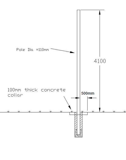
Page 32
Appendix A – Signal Pole Details
Figure 1- Standard 5 meter Pole
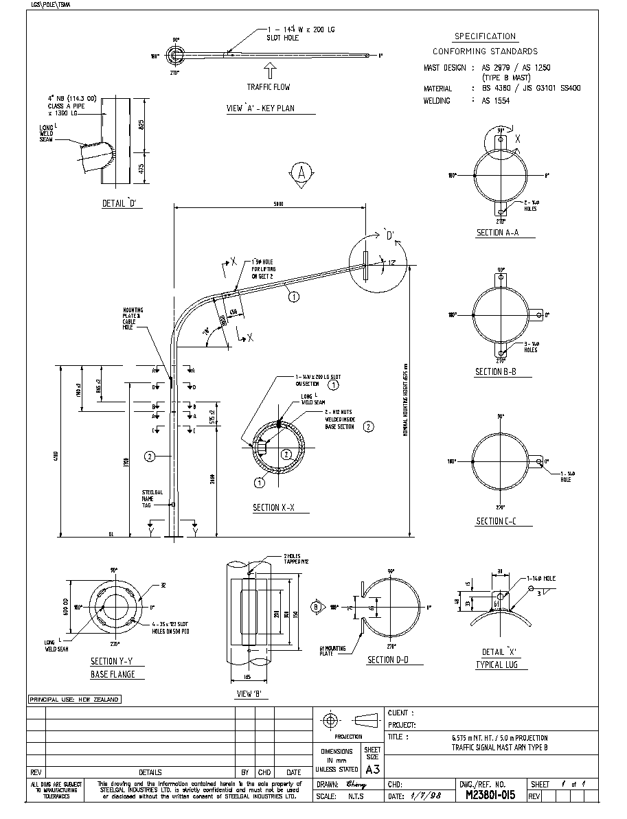
Page 33
Figure 2- Overhead Mastarm Pole
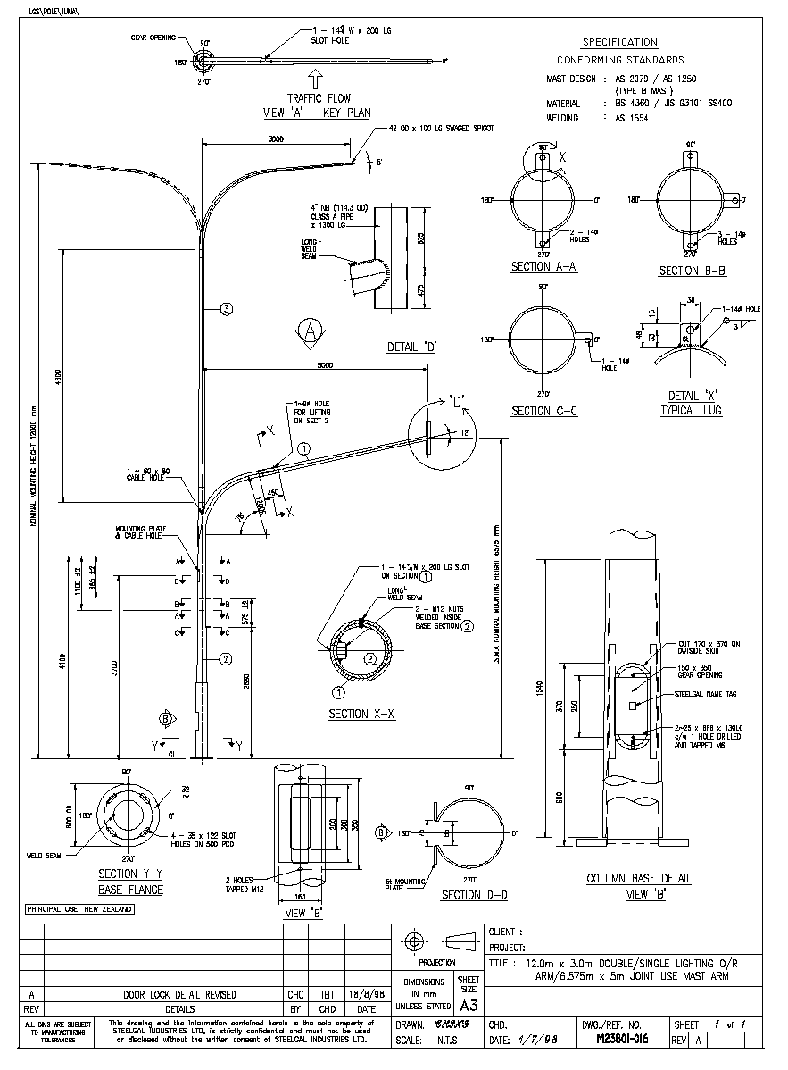

Page 34
Figure 3 - Joint Use Poles
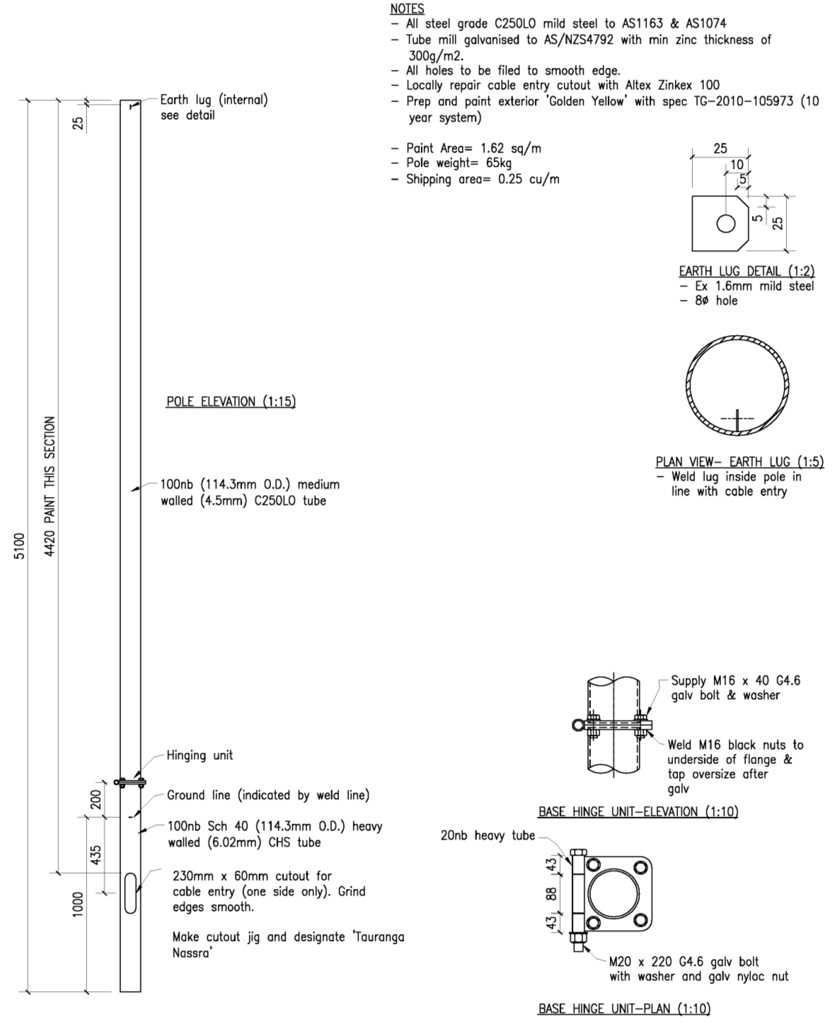
Page 35
Figure 4 - Standard 5m Fold Down Pole Detail
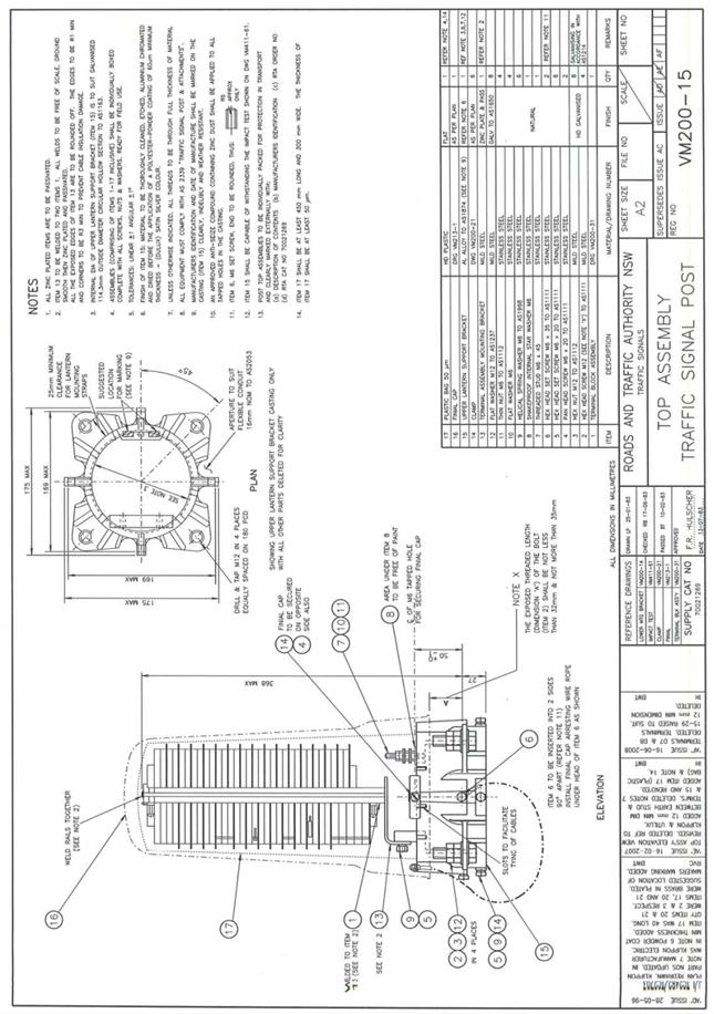
Page 36
Appendix B – 5 meter Pole Top Assembly
Figure 5 - Pole Top Assembly
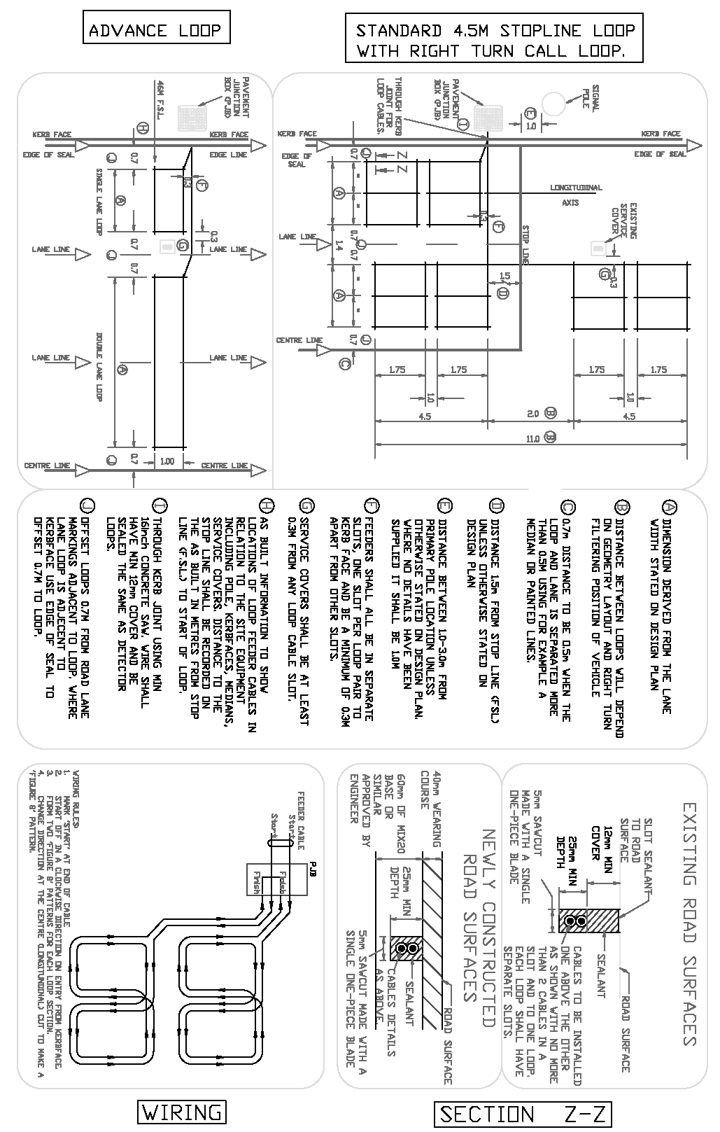
Page 37
Appendix C – Inductive Loop Layout Details
Figure 6 – Vehicle Loop Details
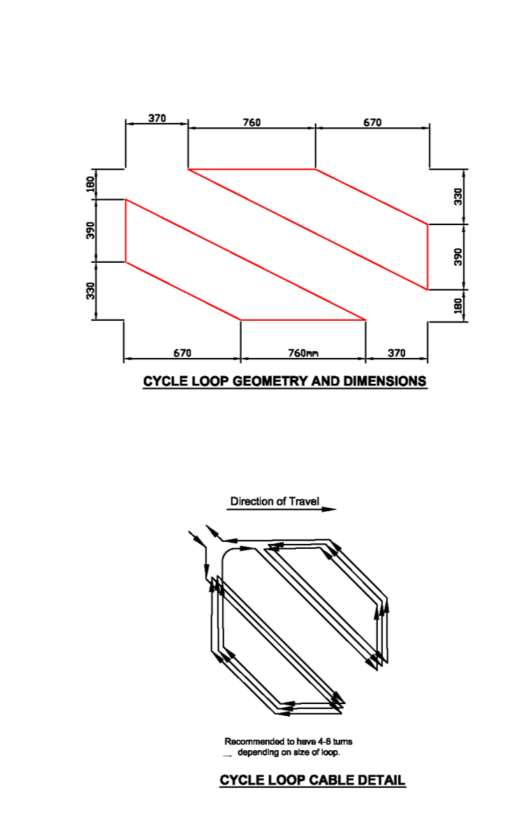
Page 38
Figure 7 – Cycle Loop Details
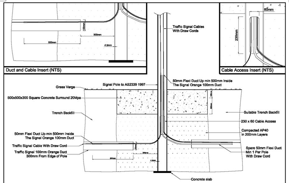
Page 39
Appendix D – Pole Duct Access Details
Figure 8 – Duct Access Details
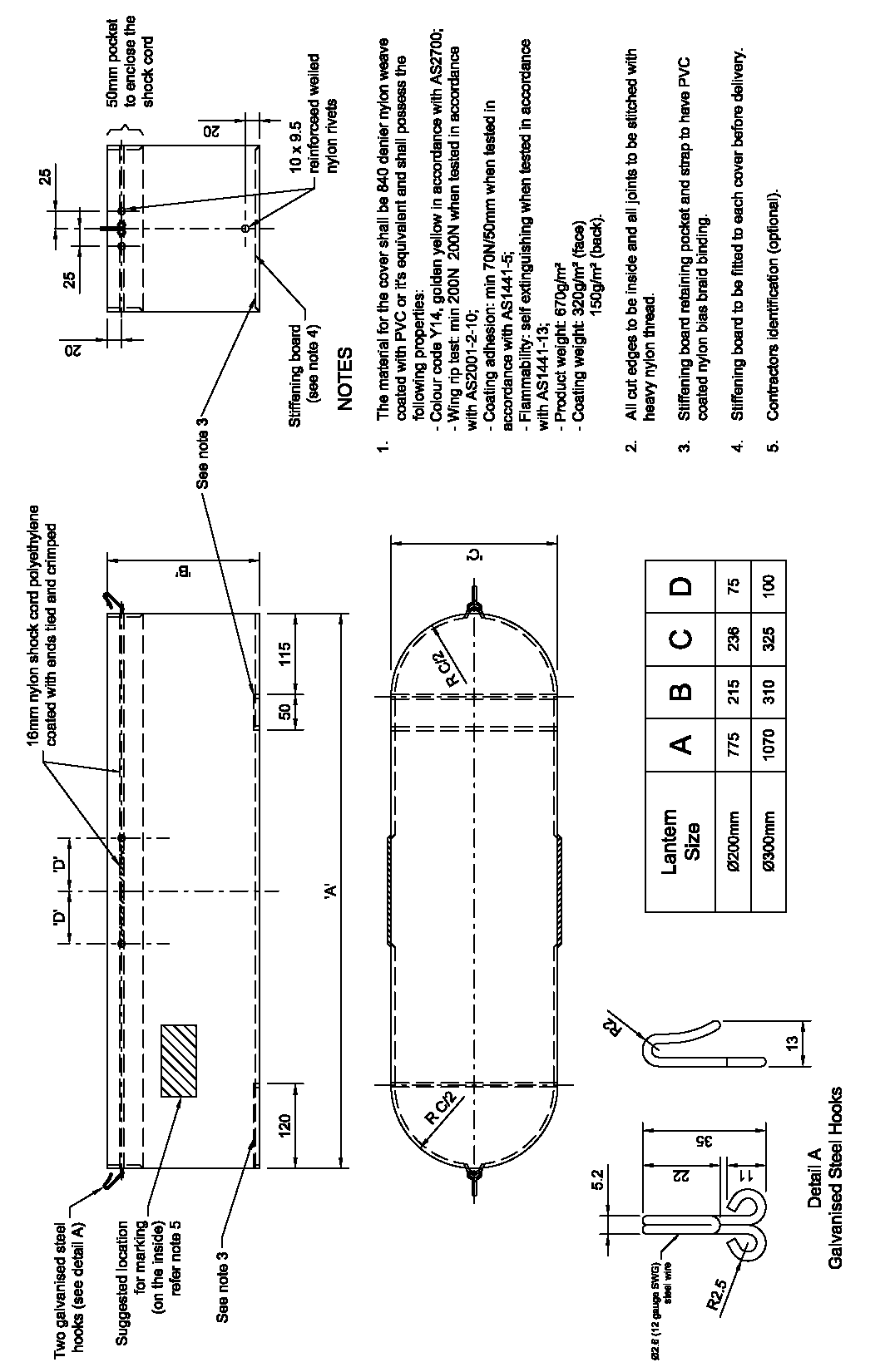
Page 40
Appendix E – Lantern Shroud Details
Figure 9 – Vehicle Lantern Shroud
Appendix F – Cable Termination Chart
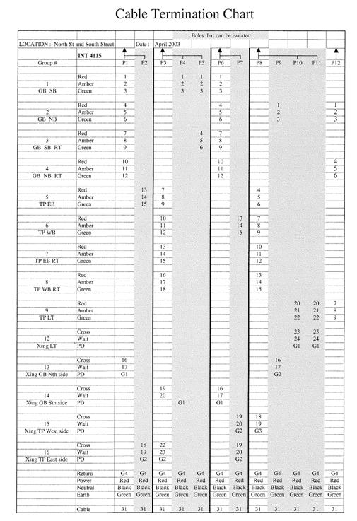
Page 41
Figure 10 – Cable Termination Chart
Appendix G – Site Acceptance Test Chart
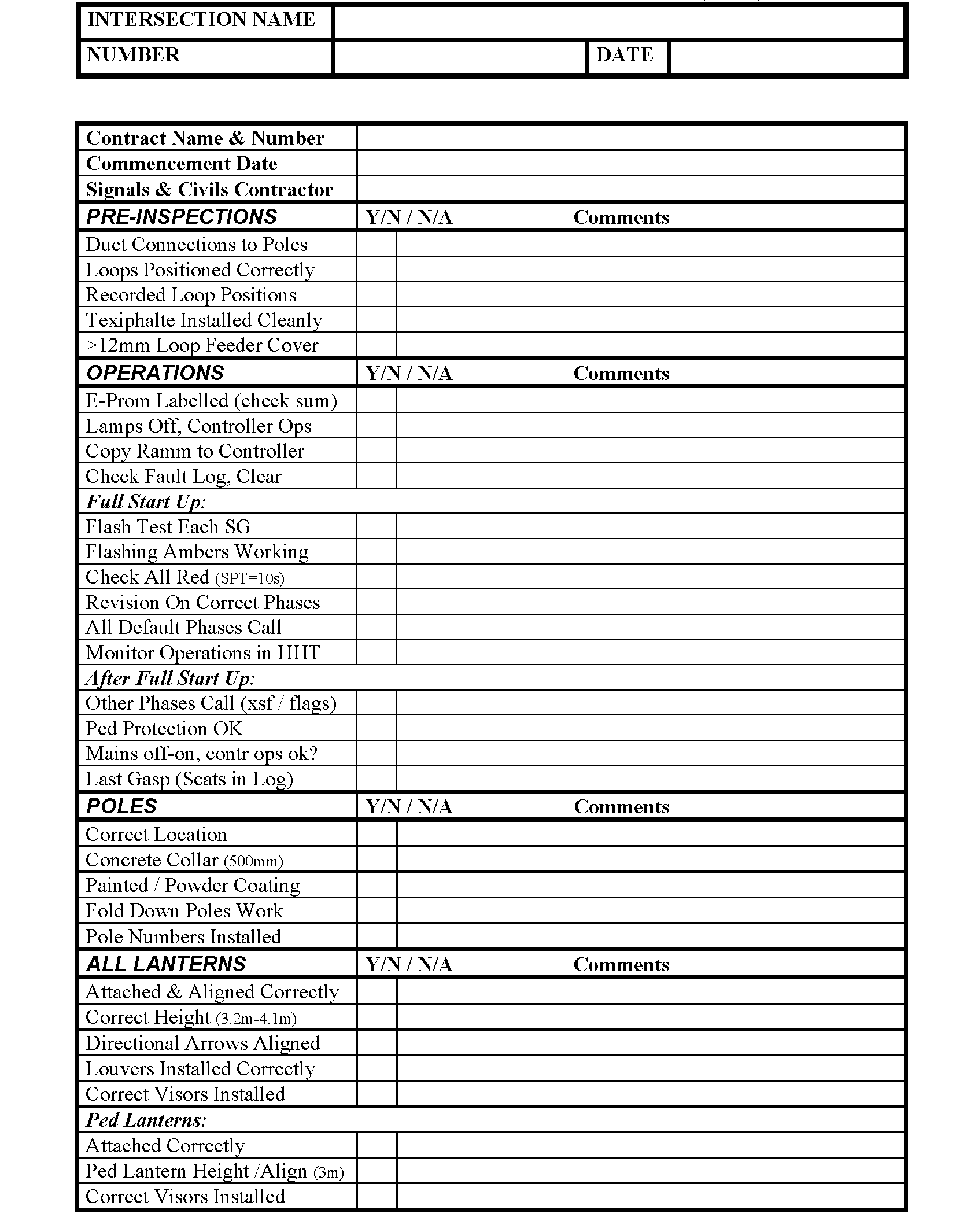
Page 42
Figure 11 – Site Acceptance Sheet 1 of 3
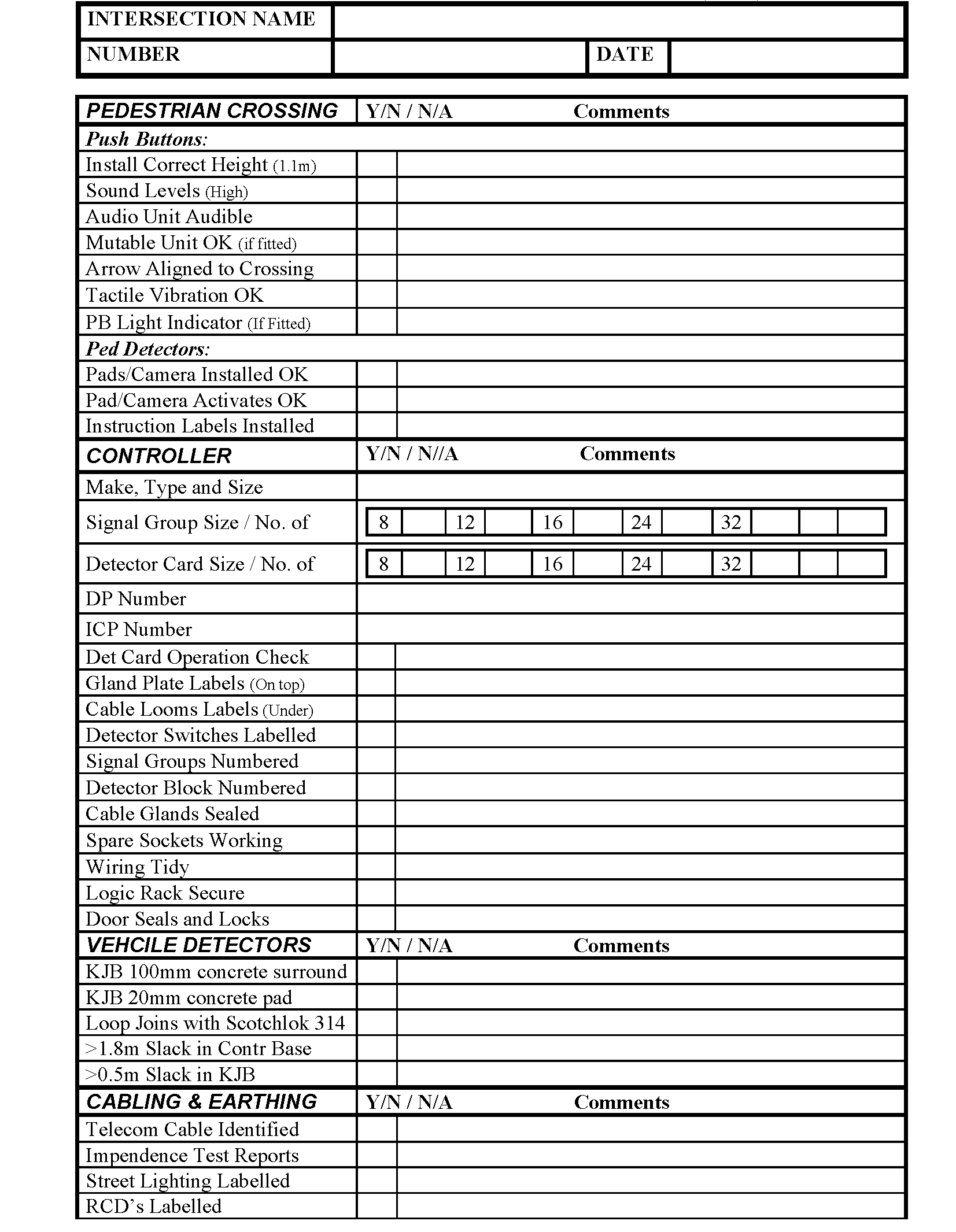
Page 43
Figure 12 – Site Acceptance Sheet 2 of 3

Page 44
Figure 12 – Site Acceptance Sheet 3 of 3
Appendix H – Controller Bench Testing Form
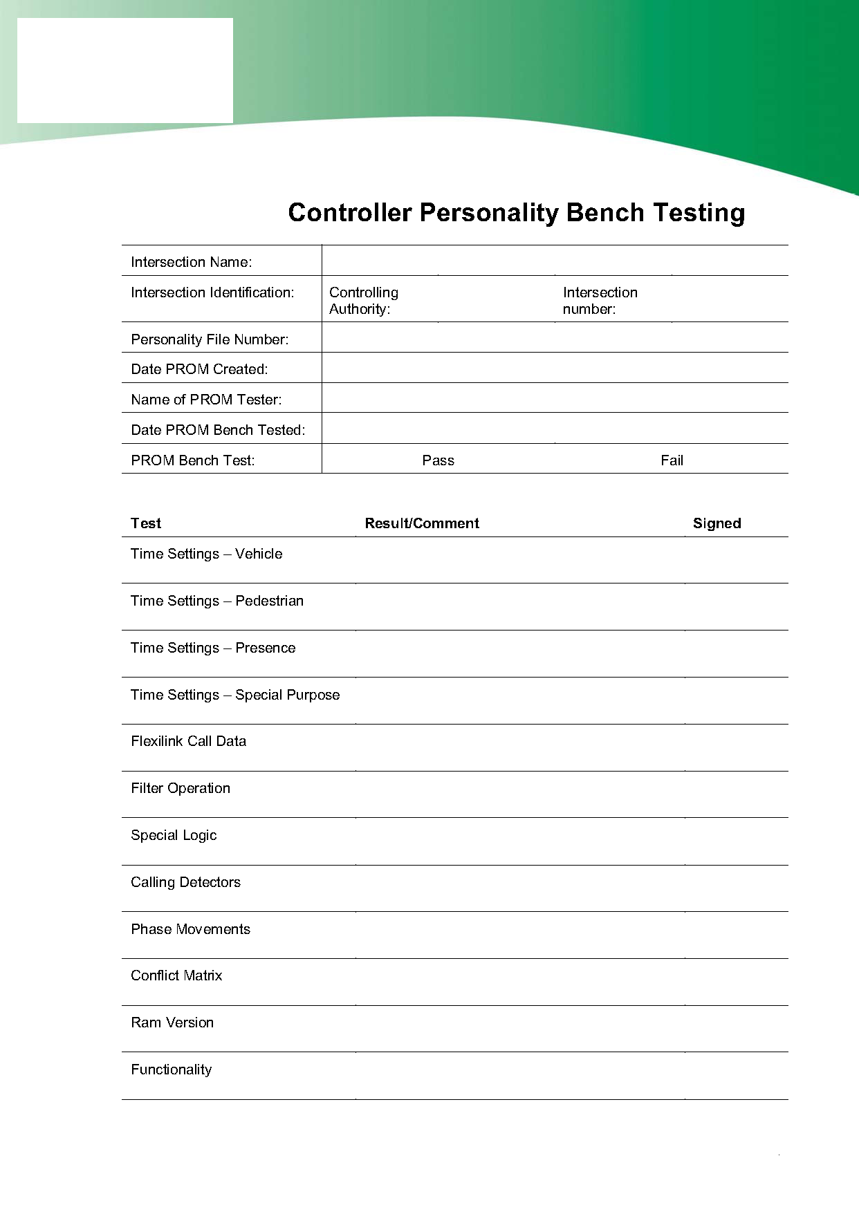
Page 45
Figure 13 – Controller Bench Test Form
Appendix I – New Intersection Commissioning Form

Page 46
Figure 14 – New Installation Check Form
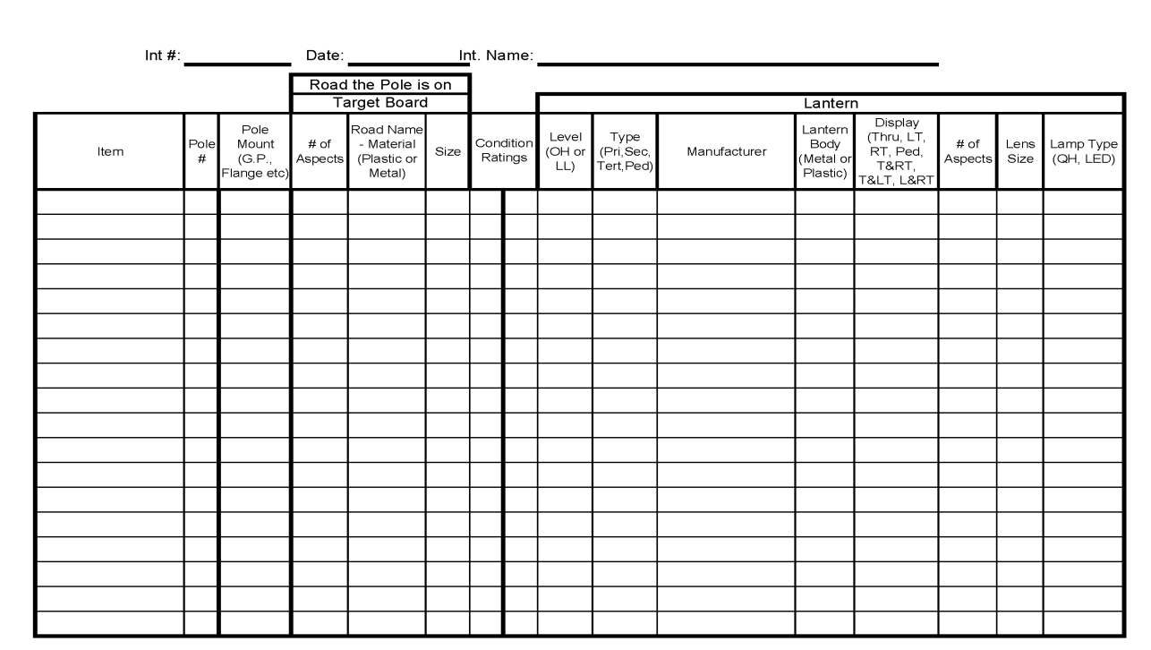
Page 47
Appendix J – RAMM Asset Data Form
Figure 15 – Asset Information Form
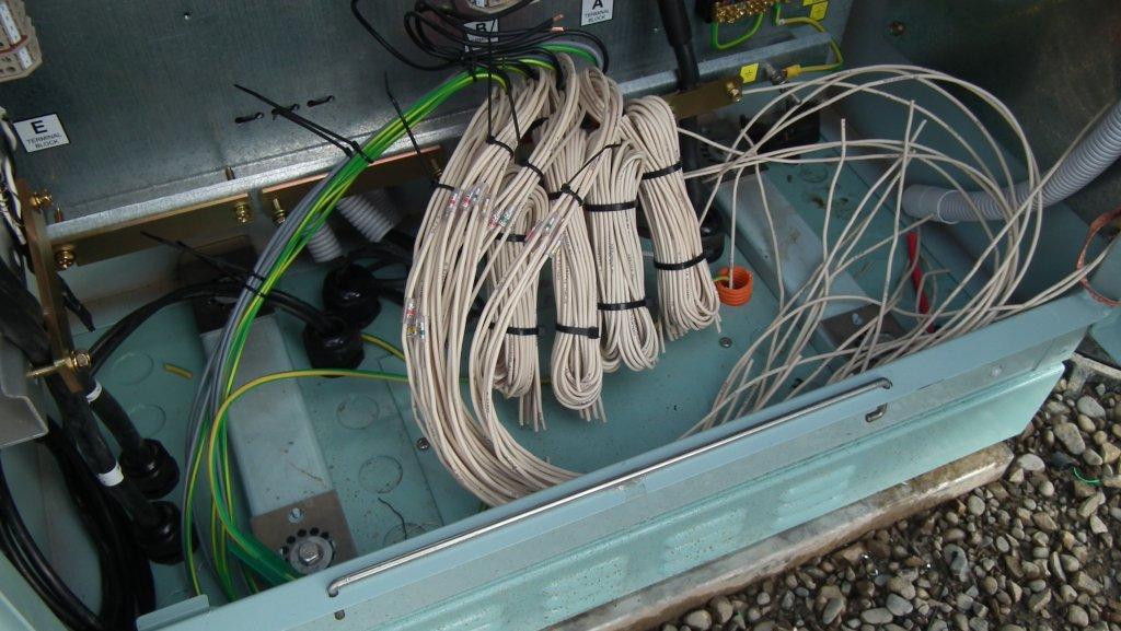
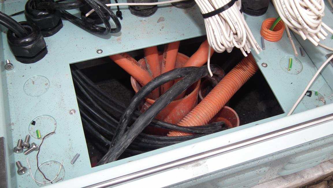
Page 48
Appendix K – Example Controller Gland Plate
Figure 16 – Showing bottom of controller with gland plate fitted and access panel fitted
FIGURE K2
Figure 17 – Showing bottom of controller cabinet with gland plate access panel removed