Act
Fire suppression guide
Information
Official
the
under
Released
September 2016
Fire suppression guide F1 GD
link to page 3 link to page 4 link to page 5 link to page 5 link to page 5 link to page 5 link to page 6 link to page 6 link to page 7 link to page 8 link to page 8 link to page 9 link to page 9 link to page 10 link to page 12 link to page 12 link to page 13 link to page 13 link to page 14 link to page 15 link to page 15 link to page 15 link to page 16 link to page 17 link to page 17 link to page 17 link to page 18 link to page 18 link to page 18 link to page 19 link to page 19 link to page 20 link to page 20
GUIDE - Fire suppression
Contents
Record of amendments ..................................................................................................... 3
About this Guide ............................................................................................................... 4
Fire Suppression ............................................................................................................... 5
First-alarm response .......................................................................................................... 5
Flashover: time and temperature ....................................................................................... 5
Size-up .............................................................................................................................. 5
Act
Fire types and techniques .................................................................................................. 6
Vented fires (fuel controlled) .......................................................................................... 6
Unvented fires (ventilation controlled) ............................................................................ 7
Partially-vented fires ...................................................................................................... 8
Impact of PPE ................................................................................................................... 8
Heat release rates ............................................................................................................. 9
Nozzle and delivery selection ...........................................................................................10
Information
Typical NZFS hose and nozzle capabilities. ......................................................................10
Class A foam ....................................................................................................................12
Fire suppression conclusions ...........................................................................................12
Pumping appliances water tanks ......................................................................................13
Official
Pumping appliance tank supply discharge times. .............................................................13
Class A foam for operational use ......................................................................................14
the
Fire suppression tools .................................................................................................... 15
Hose reels ........................................................................................................................15
Friction loss ..................................................................................................................15
under
Current specifications ...................................................................................................16
Nozzles ............................................................................................................................17
Nozzle types .................................................................................................................17
Smooth-bore straight nozzles ...........................................................................................17
Typical flows at 700 and 1050 kPa ...................................................................................18
Constant pressure-control nozzles ...................................................................................18
Released
Low-pressure nozzles ...................................................................................................19
Aspiration nozzles ........................................................................................................19
Automatic pressure-control nozzles ..................................................................................19
Older types of automatic nozzles ..................................................................................20
Sliding valve automatic nozzles ....................................................................................20
NZFS National Operations
page 2 of 26
F1 GD Fire Suppression guide September 2016
link to page 21 link to page 22 link to page 23 link to page 23 link to page 23 link to page 23 link to page 24 link to page 24 link to page 24 link to page 25 link to page 25 link to page 26
GUIDE - Fire suppression
Typical Flow Ranges ........................................................................................................21
Friction loss of delivery hose ............................................................................................22
Foam ................................................................................................................................ 23
Foam application ..............................................................................................................23
Non-aspirated ...............................................................................................................23
Aspirated ......................................................................................................................23
Foam equipment ..............................................................................................................24
Compressed Air Foam System (CAFS) ........................................................................24
Act
Aspiration nozzles ........................................................................................................24
Variable inline inductors ................................................................................................25
Friction loss per length .....................................................................................................25
Considerations for a foam delivery from an inline inductor ................................................26
Information
Record of amendments
Date
Brief description of amendment
20 Jan 2014
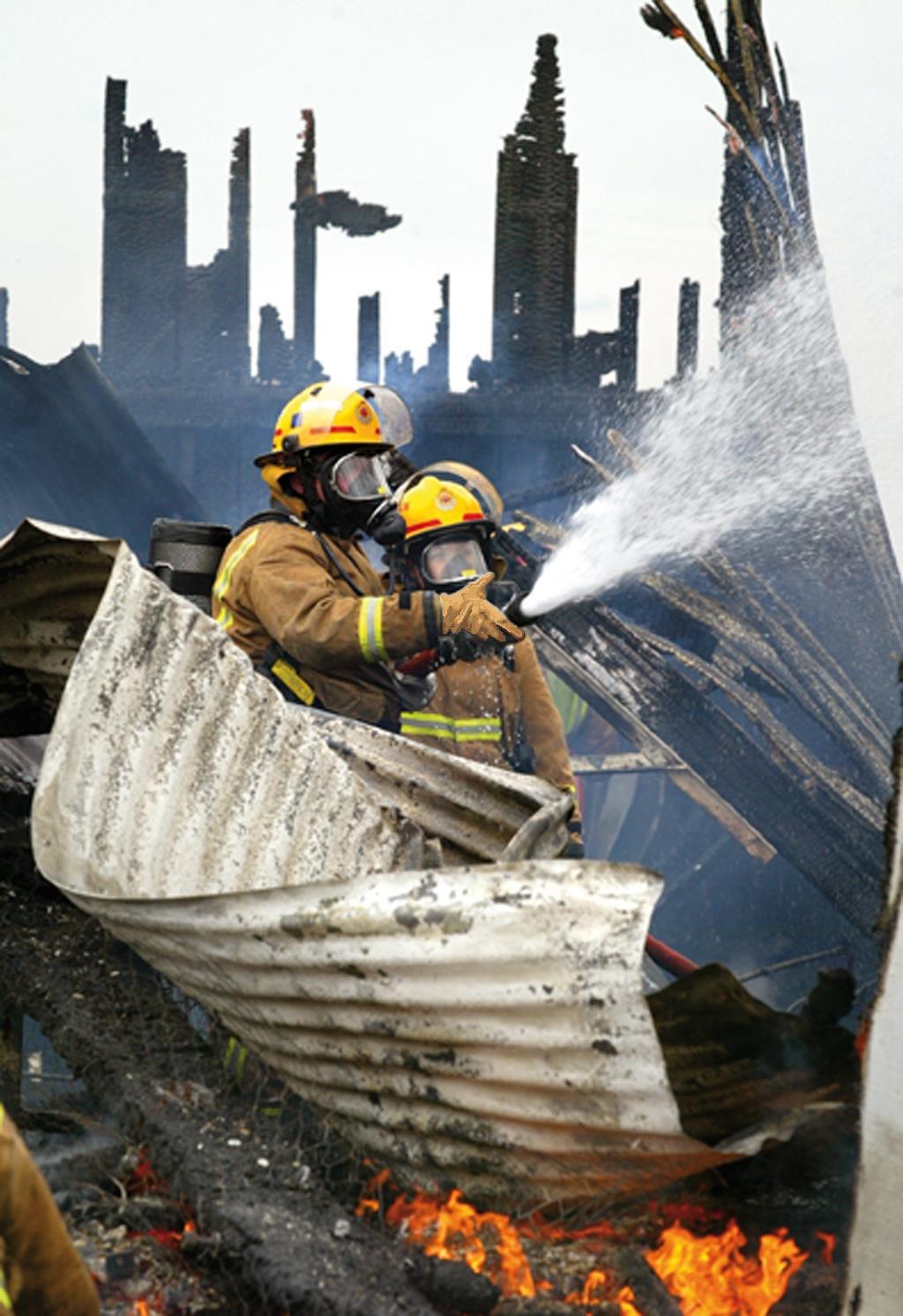
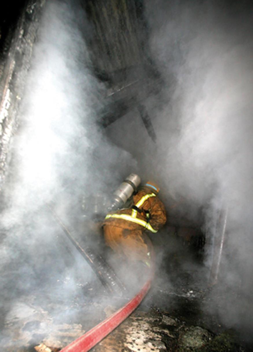
Cover images updated following staff feedback
Official
17 Mar 2014
Minor change to Class A foam page 12
3 April 2014
Minor typographical corrections.
p6 Dynamic risk assessment - ‘fire attack plan’ changed to ‘tactics’.
the
p8 Use visual signs ‘as well as’ temperature changes.
Specific fleet information for Class A foam and hose reels removed.
p15 Matching nozzle to tubing capacity - 1400 kPa pump pressure changed to ‘between 1500
and 1700 kPa.’
under
p16 Decreased throw - air ‘entrapment’ changed to ‘entrainment’
p17 Type 3 and 4 ‘flowing up to 250L/min’ changed to ‘230L/min’, ‘automatic’ added to Type 1
500 kPa nozzle and Note added to refer to appliance manual.
p23 Non-aspirated foam - rubbish, structure and vehicle fires added as uses
p25 Flammable liquid fires – added ‘Class A and Class B foams should never be mixed.’
27 Sept 2016
Broken link to TFT Ultimatic Information Note has been fixed.
Released
NZFS National Operations
page 3 of 26
F1 GD Fire Suppression guide September 2016
GUIDE - Fire suppression
About this Guide
Introduction
Firefighters work in dangerous environments where their safety and
the success of their actions is determined by training, PPE and the
most appropriate selection of fire suppression tools and medium
application.
With the increasing frequency of structure fires that result in
flashover or other forms of rapid fire progression, the importance of
carrying out an efficient risk assessment and applying sufficient
water appropriately is paramount. It is vital to get ahead of the fire
growth curve and achieve a rapid knockdown before such conditions
Act
can occur.
The flow rate of the deliveries deployed must be sufficient to cool the
high-temperature gases and smoke at the ceiling level, while at the
same time absorbing enough heat to cool the surrounding walls,
ceilings, floors, and other combustible contents, thereby avoiding
uncontrolled gas ignition or flashover.
Purpose
The purpose of this guide is to provide the minimum information
required by a firefighter to safely undertake an internal fire attack. It
Information
also describes basic NZFS fire appliance capabilities and the range
of tools and media available to firefighters for use at different types
and sizes of incidents, including Class A and B foam application.
It is important that tools and media form part of the fire attack plan
and tactical decisions so that the correct selection is made before
committing crews at an incident.
Official
Status
This document has been produced by the operational advisory team
the
at National Headquarters. Its content has been summarised from the
fire suppression sections of the Training and Progression System
(TAPS) and fleet documentation. It will be updated as new
techniques and equipment are adopted.
under
Peer review
The content of this document has been peer reviewed by:
National Advisor – Operations
TAPS subject matter experts.
Released
NZFS National Operations
page 4 of 26
F1 GD Fire Suppression guide September 2016
GUIDE - Fire suppression
Fire Suppression
First-alarm response
Importance of
New Zealand and international experience shows that first-response
preventing
crews often arrive at structural fires as they are approaching the
flashover
flashover stage. This means that the fire is approaching its maximum
heat flux and, unless it is cooled very rapidly, it can be expected to
progress to flashover. It is essential that firefighters making entry into
a structure under these conditions are equipped with a delivery that
can flow sufficient water to prevent flashover occurring.
Act
Under-equipped firefighters are less likely to prevent a flashover and
are at serious risk of harm should a flashover occur.
Flashover: time and temperature
How a flashover
As a fire develops, heat and smoke from burning contents reach the
forms
ceiling, then accumulate, mushroom out and radiate extreme heat
downward to floor level, which causes all the combustible materials
Information
in the fire compartment to reach their ignition temperature and ignite.
Structure fires often develop to flashover in significantly less than 10
minutes from ignition, as gases at ceiling height reach a temperature
of around 600°C. This development can be expected from any typical
compartment fire.
Official
Fire loading
Fire loading can vary - for example, a typical polyurethane
upholstered lounge chair burning at its peak could produce a one
megawatt (MW) fire, while a large sofa of similar construction at its
the
burning peak could produce approximately a two MW fire.
Peak heat
As the proportion of hydrocarbon-based plastics and modern
release rate
materials in furniture increases in typical homes, firefighters should
under
(HRR)
anticipate the peak heat release rate (HRR) in a room fire to be
higher than seven MW. They must also expect adjacent fully-
involved compartments to generate radiant heat levels of at least 20
kW/m2, which may affect the contents of the room from which they
are operating or into which they are directing a water stream.
Size-up
Released
Dynamic risk
All officers are required to apply the principles of dynamic risk
assessment
assessment as described in the
NZFS Incident Management
Command and Control Technical Manual (M1 TM).
The 360 degree assessment must include an analysis of:
fire loading, including construction types
compartment size and integrity (has the compartment vented?)
NZFS National Operations
page 5 of 26
F1 GD Fire Suppression guide September 2016
GUIDE - Fire suppression
fire intensity and pre-burn time
visual signs, which include pyrolysis, materials changing physical
state, the level of the neutral plane and, significantly, the effect
that water application has on those conditions.
The picture formed from this process should determine the tactics to
be used.
Inadequate
Initial tasking is often limited by the availability of resources. Where
resources
the risk to internal firefighters is determined to be too high, or where
adequate resources are not immediately available, defensive tactics Act
are the default position until the OIC determines otherwise.
Defensive attack Tasking of crews for an internal attack must include delivery and
nozzle selection that will safely control the expected heat release
rate and manage flashover potential. Where resources or inadequate
water supplies do not allow this, a defensive attack should be
initiated to limit fire spread. Other factors that should be considered
in the fire attack plan are aggressive ventilation - including the use of
PPV fans - and the use of ground, deck and aerial monitors.
Information
Fire types and techniques
Buildings over
The type of construction typically used 20 or more years ago in New
20 years old
Zealand for domestic and light industrial buildings means that the
Official
great majority of structure fires are vented and free-burning by the
time the first NZFS appliance arrives at the incident.
the
Modern
Modern construction methods and materials (such as fire-resistant
construction
linings and double-glazing) are more likely to result in unvented or
partially-vented fires.
under
Vented fires (fuel controlled)
Volume of the
In this case, the first attack delivery must be selected based on the
fire
estimated volume of the fire compartment involved, including any
compartment
possible escalation in size that may occur before water can be
applied. This will ensure that the attack team is equipped with a
delivery that has the capacity to cool the entire contents of the
compartment including ceiling, walls and floor as rapidly as possible.
Released
Full capacity
This stream should initially be used at its full capacity with the
stream
intention of knocking down the fire and minimising the production of
superheated steam, which can cause injuries to firefighters operating
inside or just outside the compartment.
NZFS National Operations
page 6 of 26
F1 GD Fire Suppression guide September 2016
GUIDE - Fire suppression
Nozzle setting
The nozzle should have a minimum flow capability of 440 L/min and
a stream pattern setting of between 30°-60°. The stream pattern
setting will depend on the penetration required to reach the seat of
the fire and the need to absorb heat.
Direct fire attack Initially the stream should be directed overhead to cool the hottest
part of the fire as quickly as possible. It should then sweep the walls
and contents to cool rapidly the primary fuel. Unvaporised water will
fall to the floor cooling the fuel there. Where necessary, the delivery
should be aggressively advanced with the flow from the nozzle
constant until the fire has been knocked down. This fire attack
Act
technique is referred to as ‘direct fire attack’.
Unvented fires (ventilation controlled)
Potential
In an unvented fire, most of the products of combustion stay within
backdraught
the compartment and the air supply for the fire comes from the
conditions
compartment alone. There may be sufficient air in the compartment
for complete combustion if the fuel source is small. If the fuel source
Information
is larger, there will be insufficient oxygen available and incomplete
combustion will occur. This can lead to backdraught conditions. If a
fire in a compartment is unvented and impending backdraught
conditions are identified, the appropriate door entry procedure and
risk assessment must be used.
Official
Indirect fire
When the first attack delivery is deployed, the use of gas cooling (as
attack
taught in compartment fire behaviour training), is the preferred
technique. This is referred to as ‘indirect fire attack’ This technique
the
provides an internal nozzle team with a method to successfully
control a developing fire when impending flashover conditions are
observed in an unvented compartment.
under
Pulses of water
It applies “pulses” of water spray of less than one second duration
spray
into the ceiling area to reduce the gas temperature. This cools the
overhead gases and prevents their ignition and consequent
flashover. When used together with application of similar “pulses”, to
the compartment linings this will reduce the temperature within the
compartment and allow crews to gain control of the fire.
Careful control
The intent is to control the heat and maintain conditions of visibility
Released by preventing flashover and gradually extinguishing the fire by
cooling and producing steam, without creating untenable conditions
for fire crews. The careful control of these conditions may be
necessary to carry out search and rescue operations.
NZFS National Operations
page 7 of 26
F1 GD Fire Suppression guide September 2016
GUIDE - Fire suppression
Monitor the
Care must be taken when using the pulsing technique to apply
environment
sufficient water to cool the fire but not disturb the neutral plane or gas
layer. The environment must be constantly monitored to ensure that
correct flow settings are used so that enough water is applied to
exceed the rate of fire growth. Once the over-pressure region is
controlled, a direct fire attack on the fire seat can be made, in
conjunction with structure ventilation.
Nozzle settings
The nozzle should have a minimum flow capability of 440 L/min and
a stream pattern setting of between 30 and 60.
Act
If the fire vents
If an unvented fire vents while this technique is being employed
then the fire should be treated as a vented fire. The use of pulsing
should cease and a direct fire attack should commence.
Partially-vented fires
Information
Fire gas
In a partially-vented fire, some of the products of combustion can exit
explosion
the fire compartment and an air supply can enter. The fire
compartment has vented, but other compartments within the
structure have not. Fire gases can accumulate in the other unvented
compartments.
This situation may create conditions that can lead to a fire gas
Official
explosion.
Impact of PPE
the
Use visual signs
Modern PPE better protects firefighters from the high temperatures
generated in compartment fires. This high level of protection
decreases sensory awareness and, in cases of very low visibility, it is
often difficult to observe flames in the overhead, or other visual
under
clues. When assessing the risk of a compartment while wearing
modern PPE, it is important that crews use visual signs of fire
development as well as feeling temperature changes.
Importance of
Poor risk assessment may cause firefighters to over-commit to an
risk assessment
internal position. This could result in them being in a position where
their delivery flow rate does not have the heat-absorbing capability to
Released prevent or stop the fire’s progression. In this situation, crews could
be exposed to flashover.
Survival time in
NZFS PPE allows approximately 20 seconds survival time in flashover
flashover
conditions.
NZFS National Operations
page 8 of 26
F1 GD Fire Suppression guide September 2016
GUIDE - Fire suppression
Heat release rates
Estimating HRR at
Average residential fuel loads now have a maximum heat release
flashover
rate (HRR) under flashover conditions of about 0.77MW/m2. This
figure can be used to estimate maximum potential heat flux of any
compartment based upon its area. For example, a fire that has
flashed over in a room 3m x 3m - similar to that of a small
bedroom fire - can be estimated to produce a peak HRR at
flashover of seven MW. In an open plan lounge living area that
measures 6m x 6m, a peak HRR of 28 MW can be estimated
(see table below).
Act
Typical Heat Release Rates
Room dimensions
m2
Estimated peak HRR
3m x 3m
9
7 MW
4.5m x 4.5m
20
15.5 MW
6m x 6m
36
28 MW
Information
9m x 9m
81
63 MW
Heat-absorbing
The theoretical capacity of water to absorb heat (latent heat of
capacity of water
vaporization) defines the maximum potential HRR that a given
amount of water can absorb. For practical purposes, a fog
Official
stream operating on a 600C fire has a heat-absorbing efficiency
of 75%, and a smooth bore stream has a heat-absorbing
efficiency of 50%.
the
Critical flow rate
If the heat-absorbing capability, or knockdown power, of the flow
rate is greater than the heat produced by the fire, the fire will go
out. This is referred to as the “critical” flow rate.
Tactical flow rate
When the 25% efficiency loss of a fog stream (or the 50% loss of
under
a straight stream) is taken into account, this is referred to as the
"tactical flow rate".
Note: Additional flows may be required for exposure protection.
Released
NZFS National Operations
page 9 of 26
F1 GD Fire Suppression guide September 2016
GUIDE - Fire suppression
Nozzle and delivery selection
Small and medium
Deliveries with nozzles capable of flowing 440-550 L/min can
fires
safely control flashover in small and medium fire compartments
with normal fire loading. They will also prevent the rapid build-up
of steam that often occurs when lower flow rates are used, for
example a hose reel.
Large fire
A 70mm delivery fitted with 880-970 L/min nozzles should be used
compartments/high for larger fire compartments with high fire loading. These
fire loading
deliveries are often supported with high-flow ground, deck, and
aerial monitors.
Act
Typical NZFS hose and nozzle capabilities
Hose
Flows
Typical nozzles
Heat absorbing
capability
25 mm hose reel
180-220 L/min
TFT Utimatic 125 14-17 MW
nozzle (hose reel)
Akron 1702
Elkhart Phantom
Information
45 mm delivery
440-550 L/min
Elkhart 125
34-42.3 MW
nozzle (light
TFT Qudracup
delivery)
70 mm delivery
880-970 L/min
Elkhart 250
67-74 MW
Official
nozzle
(heavy delivery)
the
Approximate tactical flows required to obtain a rapid knock down related to
compartment size
Compartment
Floor area
Peak heat
Gross flow
Typical
type (fully
(2.4m stud)
release rate
delivery
under
(litres per
involved)
(megawatts)
minute)
required
Bedroom
9m2
7 MW
90 L/min
1 x hose reel
Lounge/dining
20m2
16 MW
200 L/min
1 x hose reel or
1 x 45 mm
delivery
Released
Large garage
36m2
28 MW
360 L/min
2 x hose reels or
1 x 45 delivery
Small house
100m2
77 MW
1,000 L/min
2 x 45 mm
deliveries or
1 x 70 mm
delivery
NZFS National Operations
page 10 of 26
F1 GD Fire Suppression guide September 2016
GUIDE - Fire suppression
Average house
150m2
115 MW
1,500L/min
3 x 45 mm
deliveries
Large house
200m2
154 MW
2,000 L/min
4 x 45mm
deliveries or
2 x 70 mm
deliveries
Size up and
From the tactical flow table it can be calculated that, for every square
calculate tactical metre of area involved, a flow of about 10 litres per minute is
flow
required to achieve rapid knockdown. This allows officers doing their
360-degree survey to very easily size up a fire and calculate the
Act
required flow rate.
For example: A 360-degree survey of a house fire indicates that the
area involved in fire is approximately 5m x 8m. 5 x 8 equals 40 m2 x
10 L/min = 400 L/min. In this case, deploy two hose reels or one 45
mm delivery with the nozzle set at 400 L/min or higher.
Information
Official
the
under
Released
NZFS National Operations
page 11 of 26
F1 GD Fire Suppression guide September 2016
GUIDE - Fire suppression
Class A foam
Use for fully
Class A foam (non-aspirated, nozzle-aspirated and Compressed Air
vented fires or
Foam Systems or CAFS) will knock down normal combustibles faster
defensive
than fog streams. Class A foam is most suitable for fully-vented fires
external attack
where flashover has already occurred or is no longer possible, and
for defensive external fire attack.
For offensive internal attack on unvented or partially-vented
compartments, the minimum nozzle flows of 440 L/min must not be
reduced. This is the recommended flow that is required for the
control of flashover.
Act
Don’t use CAFS
CAFS deliveries will not provide adequate flows or the narrow and
for large
wide pattern capability required for firefighter protection against
compartments
flashover in large compartment fires. The Quadracup aspiration
nozzle will.
CAFS is suitable for defensive attacks.
Features of
Water delivery
Class A solution
Class A aspirated
Information
delivery methods
delivery
delivery
Foam setting (%)
na
0.3
0.5
Water flow (L/min)
360
360
360
Knockdown time
50
25
14
Official
(seconds)
Knockdown water
280
160
80
the
(litres)
Temperature drop
6:03
1:45
1:30
from 315oC to 93oC
(Minutes: seconds) under
These figures are taken from a Los Angeles County Fire Department burn trial using three
identical furnished 100 m2 structures with the same pump, crew and contents.
Fire suppression conclusions
All firefighters are required to have knowledge of the delivery and nozzle capabilities used in
compartments found in residential fires. They should understand tactical and critical flow
Released
rates and be able to apply the direct and indirect fire attack firefighting techniques on vented,
unvented and partially-vented fires. They should understand the different media and be able
to select the correct equipment to apply them.
NZFS National Operations
page 12 of 26
F1 GD Fire Suppression guide September 2016
GUIDE - Fire suppression
Pumping appliances water tanks
Water tank
Water tanks should contain enough water for:
requirements
the protection of crew undertaking a snap rescue at a structure or
vehicle fire, HazMat incident or an accident
the initial knockdown at structure and vegetation fires to limit fire
growth until a secondary water supply is established
extinguishing a small structure or vehicle fire (some heavy
vehicles will require secondary water supplies)
extinguishing typical small outdoor rubbish and miscellaneous
fires
Act
supplying water for emergency decontamination.
Tank size
Larger water tanks will extend the time for secondary water supplies
to be provided. Typically, appliances with a rural risk have larger
water tanks.
Flow rates
A minimum of 440 L/min is required for initial fire attack in a structure
Information
fire with one room fully involved. A minimum of three minutes
continuous flow is a guide for rapid knockdown.
Water
Non-aspirated Class A foam is 100% more effective than water, and
conservation
aspirated Class A foam is 300-500% more effective than water.
When water conservation is necessary, using foam will proportionally
Official
decrease suppression times or allow lower flows of water to be used,
without reducing extinguishment effectiveness.
the
Pumping appliance tank supply discharge times.
Tank
Type 1
Type 2
Type 3
Type 4
discharge
times
under
Tank size in
2000
1800
1350
1350
litres
Note: FFR T2
have 2000 litre
tanks
Hose reels
1 x 180
1 x reel at
1 x reel at
1 x reel at
L/min lasts
220 L/min
220 L/min
220 L/min
11 minutes
lasts 8
lasts 6
lasts 6
Released
minutes
minutes
minutes
2 reels lasts 2 reels lasts 2 reels lasts
4 minutes
3 minutes
3 minutes
Light delivery
4.5 minutes
4 minutes
3 minutes
3 minutes
440 L/min
NZFS National Operations
page 13 of 26
F1 GD Fire Suppression guide September 2016
GUIDE - Fire suppression
Class A foam for operational use
Class A induction
Compound used for:
rate and
applications
Hose reel or delivery Light delivery rated
Two light deliveries
rated at 220 L/min
at 440 L/min
rated at 880 L/min
Wetting agent 0.2% Uses 0.4 L/min.
Uses 0.8 L/min.
Uses 1.7 L/min.
(range 0.1%-0.2%)
A 20-litre foam
A 20-litre foam
A 20-litre foam
Induction rate used
container will
container will
container will
for vegetation fires
last 45 minutes.
last 22.5
last 11 minutes.
and overhaul. Use
Act
minutes.
normal nozzles.
Wet foam 0.5%
Uses 1.1 L/min.
Uses 2.2 L/min.
Uses 4.4 L/min.
(range 0.3%-0.5%)
A 20-litre foam
A 20-litre foam
A 20-litre foam
Induction rate used
container will
container will
container will
for fires in trees,
last 18 minutes.
last 9 minutes.
last 4.5 minutes.
structures and
transport. Normal
Information
nozzles OK -
aspiration nozzles
produce superior
foam.
Official
Dry foam 1%
Uses 2.2 L/min.
Uses 4.4 L/min. Uses 8.8 L/min.
(range 0.6%-1%)
A 20-litre foam
A 20-litre foam
A 20-litre foam
the
Induction rate used
container will
container will
container will
for exposure
last 9 minutes.
last 4.5 minutes.
last 2.2 minutes.
protection.
Use aspiration
nozzles.
under
Notes:
1. The 60-litre inbuilt foam tank will last three times longer than the 20-litre container
figures.
2. A slight variation of the induction rate has little effect on the quality of the foam.
Released
NZFS National Operations
page 14 of 26
F1 GD Fire Suppression guide September 2016
GUIDE - Fire suppression
Fire suppression tools
Hose reels
Background
In the early 1970s, high-pressure pumps and hose reels made their
appearance on New Zealand Fire Service pumping appliances. Hose
reels were generally fitted with three 30m lengths of 25mm smooth-
bore tubing combined with an Elkhart SFS 700 kPa constant-
pressure control nozzle. These nozzles have selectable flows rated
at 10, 20 and 30 US gallons per minute, which equate to 38, 76 and
114 L/min.
Act
Over time, successive generations of firefighters were trained in this
standard configuration.
Friction loss
The friction loss in 25mm hose reel tubing is considerable. As flow increases friction loss
increases.
Flow in litres per minute
Friction loss in kPa per 30m
Information
length of 25mm hose reel tubing
60
100
120
155
180
505 Official
240
925
the
Overcoming
To achieve the designed nozzle pressure, pump pressure must be high
friction loss
enough to overcome friction loss The practical flow rate of 25mm hose
reel tubing is approximately 250 L/min.
under
Matching nozzle
The Elkhart SFS (design nozzle pressure 700 kPa) has a flow at 700
to tubing
kPa of 114 L/min. Testing has shown that the Elkhart SFS will typically
capacity
flow 114 L/min at pump pressures between 1500 and 1700 kPa. It can
be seen that this nozzle is not matched to the capacity of the hose reel
tubing supplying it.
Released
Increased nozzle If, for example the pump is run at 3500 kPa, the nozzle will have a
pressure
nozzle pressure of around 2200 kPa where it is designed to run at
700kPa. This increased pressurisation also occurs when lower flows are
selected on the nozzle, without proportionally lowering the pump
pressure.
NZFS National Operations
page 15 of 26
F1 GD Fire Suppression guide September 2016
link to page 19
GUIDE - Fire suppression
Optimum nozzle
The practice of regularly operating the hose reel, fitted with the SFS
pressure
Elkhart nozzle, well above its optimum nozzle pressure has created an
incorrect perception that the Fire Service operates high-pressure
deliveries. The SFS Elkhart is in fact a low-pressure nozzle and should
be operated accordingly.
Effects of over-
Over-pressurisation has three key adverse effects:
pressurisation
Water droplet size reduces to below the optimum 3–4
microns.
Act
While smaller water droplets can be desirable for indirect
cooling of hot gases in unvented compartments, they are
not suitable for direct fire attack. Smaller droplets may also
produce excessive steam, creating a harsher environment
for firefighters and an untenable environment for trapped
occupants.
As the nozzle pressure increases, jet reaction
increases.
This has the effect of making the hose reel difficult to
Information
manoeuvre and handle. The higher velocity of the water
will also entrain larger volumes of air. This high velocity
water can cause damage to property not involved in the
combustion.
Decreased throw
Official
As the velocity and air entrainment increases, the throw
lessens and considerable feathering of the jet will occur.
the
Optimum flow
When using selector flow nozzles, the pump pressure needs to be
adjusted whenever the flow is reduced manually at the nozzle in order
to maintain optimum flow. This is not practical when two hose reels
are in use.
under
To overcome this issue and to achieve the optimum flow available
from hose reels, automatic pressure control nozzles which have a flow
range of 40-500 L/min are fitted to all new fleet. An automatic
pressure control nozzle will automatically manage the flow over its full
flow range.
See ‘Automatic pressure control nozzles’ on page
19 and the
TFT
Ultimatic Hose Reel Nozzle Information on FireNet under General
operational equipment.
Released
Current specifications
On new pumping appliances built since 2005, a pre-connected hose reel system is configured
when the appliance is built. This system matches the capability and configuration of the pump
with the overall hose reel length and the nozzle.
NZFS National Operations
page 16 of 26
F1 GD Fire Suppression guide September 2016
GUIDE - Fire suppression
Current fleet specifications
Types 3 and 4
Type 2
Type 1
Twin hose reels supplied
Twin hose reels supplied
Single hose reel supplied
from a high pressure pump
from the main pump with:
from the main pump with:
with:
2 x 30m lengths
2 x 30m lengths
3 x 30m lengths
an automatic 500 kPa
an automatic 500 kPa
an automatic 700 kPa
nozzle
nozzle
nozzle
flowing up to 220 L/min
flowing up to 220 L/min
flowing up to 230L/min
at 1750 kPa.
at 1750 kPa.
at 3500 kPa.
Act
Note: These figures will vary depending on the pump. Refer to the appliance manual.
Nozzles
Nozzle types
Three types
The Fire Service uses three types of nozzles:
Smooth-bore straight
Information
Constant pressure-control
Automatic pressure-control.
Light or heavy
Nozzles with flow ranges up to 500 L/min should be connected to a 45
delivery
mm branch length delivery (light delivery). Nozzles with a flow range
up to 1000 L/min should be connected to a 70 mm delivery (heavy
Official
delivery).
the
Smooth-bore straight nozzles
Size
Typical sizes range from 12mm to 32mm.
under
Features
These nozzles have a tapered bore and are screwed to a tapered
branch. The branch has a formed instantaneous coupling at the other
end.
Flow
The flow is determined by the diameter of the nozzle and the nozzle
pressure.
Typical use
They are not now used on deliveries but are occasionally used on
Released monitors and for water testing. There is no on/off or stream pattern
capability. They produce a very good straight stream but modern
master stream constant pressure control nozzles are comparable.
NZFS National Operations
page 17 of 26
F1 GD Fire Suppression guide September 2016
GUIDE - Fire suppression
Typical flows at 700 and 1050 kPa
Nozzle size in mm
Flows in L/min at 700 kPa
Flows in L/min at 1050 kPa
12
250
300
15
400
490
20
700
860
25
1100
1350
Act
Constant pressure-control nozzles
Adjustable flow
These nozzles have a bore that can be reduced in diameter manually
selector
by adjusting the flow selector. Typically the flow selector will have
division at 110, 230, 360 and 470 L/min.
Connections
These nozzles may be directly connected to an instantaneous
coupling or hose reel tubing or connected to a branch. They are the
Information
most common nozzle type used on 45 and 70 mm deliveries.
Designed
The optimum flow and stream is achieved when the nozzle is run at its
pressure
designed pressure. This has typically been 700 kPa but many newer
nozzles operate at 500 kPa.
Official
Selecting lower
When lower flows are required, the manual flow selector is rotated
flows
the
and the pump pressure should be adjusted accordingly to maintain
the designed nozzle pressure.
Debris
Many nozzles have a flush facility on the flow selector. This enables
small debris to pass through the nozzle. To prevent large debris from
under
entering the nozzle, many later nozzles are fitted with a grabber
screen at the coupling.
Stream pattern
The stream pattern can be adjusted by rotating the front bumper, and
control
a lever-operated ball valve controls the on/off function. This valve is
not designed for flow control by gating, as severe nozzle turbulence is
created.
Released
NZFS National Operations
page 18 of 26
F1 GD Fire Suppression guide September 2016
GUIDE - Fire suppression
Low-pressure nozzles
Used on aerials
Low-pressure 500 kPa nozzles have typically been used on aerial
appliance monitors where head loss and waterway friction loss
constrain flows, particularly where we limit inlet pressures to 1050
kPa. Flow is more important than throw as an aerial is generally
already elevated. Ground and deck monitors typically have 700 kPa
nozzles as throw is more important as they are projecting at ground
level.
Other uses
In the case of hand-held deliveries and hose reels, low-pressure
nozzles are now common. It is important that low-pressure nozzles Act
are fitted to multi-storey deliveries.
Advantages
Advantages of low-pressure nozzles:
Required flow at lower pressures
Less jet reaction
Lower pump revolutions, hence less noise and less wear.
Disadvantage
The disadvantage is reduced throw, however the reduction is
Information
minimal and not considered important except on deck and ground
monitors.
Aspiration nozzles
Official
Ability to
A modern addition to the constant-pressure control nozzle is the
aspirate foam
ability to aspirate both Class A and B foams. Foam is inducted either
the
through the Foam Pro system or from an inline inductor. These
nozzles are a normal fire attack nozzle with the additional feature of
a retractable foam aspiration sleeve.
TFT Quadracup
The TFT Quadracup aspiration nozzle is currently the Fire Service’s
under
aspiration nozzle selected nozzle for use on a 45 mm light delivery. It is a low-pressure
500 kPa nozzle.
Automatic pressure-control nozzles
Uses
The Fire Service uses automatic nozzles on aerial, deck and ground
monitors and hose reels.
Released
Mechanism
Automatic pressure-control nozzles will provide a relatively constant
nozzle pressure throughout their flow range. In simple terms, an
automatic nozzle achieves this by having a spring-controlled baffle
fitted within the bore. As water pressure increases, the baffle is
forced open against the predetermined spring pressure, allowing
increased flow but retaining a relatively constant pressure.
NZFS National Operations
page 19 of 26
F1 GD Fire Suppression guide September 2016
GUIDE - Fire suppression
Nozzle pressure
Typically, a 700 kPa hand-held nozzle with a flow range of 40–500
L/min will have a nozzle pressure of 400 kPa-850 kPa throughout the
flow range.
Performance
As long as the nozzle is operating within its designed range, the
droplet size, jet reaction and throw will be efficient and effective.
Older types of automatic nozzles
Reduce flow by
The older types of hand-held automatic nozzles are fitted with a
Act
reducing nozzle
lever-operated ball-type on/off valve. This valve is not designed for
pressure
flow control by gating as severe nozzle turbulence is created. The
correct way to reduce flow with these nozzles is to reduce nozzle
pressure. This is difficult to control at the pump due to
communication limitations with the pump operator, and when multiple
deliveries are in use.
Sliding valve automatic nozzles
Information
Mechanism
This automatic nozzle is able to regulate flow manually while
retaining a relatively constant pressure. It achieves this by having a
sliding valve that limits the incoming water, but allows flow to
maintain a relatively constant pressure against the spring-controlled
baffle.
Official
How to operate
This flow is regulated by the firefighter moving the valve handle
through six detent positions from fully-opened to closed. This is not a
the
ball valve and does not disturb the quality of the water stream. This
allows multiple deliveries or twin hose reels to operate independently
when being supplied from the same source.
under
Caution at high
When set on the lowest detent positions and operating at high pump
pump pressures
pressures, generally over 2500 kPa, the valve handle will become
very sensitive. Care is needed when shutting down in these
circumstances. If the nozzles are to be used for long periods at low-
flow settings, the pump pressure should be reduced.
Released
NZFS National Operations
page 20 of 26
F1 GD Fire Suppression guide September 2016
GUIDE - Fire suppression
Typical Flow Ranges
To 4800
1000
Act
950
900
850
800
750
Information
700
650
600
Official
550
500
the
450
400
350
under
300
250
200
150
Released
100
50
Litres/
Hose reel
45mm light
70mm heavy
Aerial, deck and
delivery
delivery
ground monitors
minute
NZFS National Operations
page 21 of 26
F1 GD Fire Suppression guide September 2016
GUIDE - Fire suppression
Friction loss of delivery hose
Flow in
Loss per length of 45mm
Loss per length of 70mm
Litres/min
delivery hose in kPa
delivery hose in kPa
60
2.25
0.21
120
9
1
180
20
2
240
36
3
Act
300
56
5
360
81
8
420
110
10
480
144
14
540
182
17
Information
600
225
21
660
272
25
720
324
30
780
380
35
Official
840
441
41
the
900
506
47
960
576
54
under
Released
NZFS National Operations
page 22 of 26
F1 GD Fire Suppression guide September 2016
GUIDE - Fire suppression
Foam
Foam application
Non-aspirated
Low induction
The predominant use of Class A foam in the Fire Service is at a low
rate
induction rate of between 0.1 and 0.2 %. This ratio reduces the
surface tension and softens the water, which promotes greater
penetration and absorption.
Act
Uses
Generally it is used for organic type fires, typically scrub, grass and
most ground growth, and is exceptionally good for deep-seated fires,
including rubbish. It can also be used on structure and vehicle fires.
This application method provides superior heat absorption to straight
water. Time of knockdown and water usage is reduced.
‘Foam Pro’
All post-2005 NZFS fire appliances are fitted with 'Foam Pro' Class A
foam systems and are capable of producing foam from hose reels
and dedicated delivery outlets or forestry outlets. Minimal aspiration
Information
takes place and all types of nozzles can be used.
Aspirated
Aspirated foam
Class A foam can be aspirated at the induction point or at the nozzle.
Official
Foam is inducted from 0.3% to 0.5% and mixed with air. The
resultant aspirated foam mixture has the ability to:
cling to surfaces, thereby creating a non-flammable barrier
the
exclude air from cavities, so preventing fire spread and radiated
heat absorption.
The higher the foam ratio the dryer the resultant foam produced.
under
Features
Typically at 0.3% to 0.4% the foam will penetrate foliage, flows easily
and has moderate drain times. At 0.4% to 0.5 % the foam will have
poor penetration but will cling to surfaces and has slow drain times.
Uses
This thick foam is extremely effective on standing trees, gorse and
scrub, but can also be used for normal combustibles. Vehicle fires
and structure fires can easily be attacked externally via windows and
doors. This is most effective when water supplies are poor and
Released conservation is necessary.
Crews in
Aspirated foam will provide rapid control of a fire until further water is
defensive mode
obtained. There is a noted benefit in areas with minimal crewing and
or short crewing. Generally these crews would operate in defensive
mode. Careful reapplication and damping down is required for final
extinguishment.
NZFS National Operations
page 23 of 26
F1 GD Fire Suppression guide September 2016
GUIDE - Fire suppression
Environmental
The environmental impact of Class A foam used at induction ratios of
impact
0.1% to 1% is considered to be low.
Foam equipment
NZFS personnel aspirate foam at the pump by using compressed air foam systems (CAFS)
or at the nozzle using aspiration nozzles.
Compressed Air Foam System (CAFS)
Act
CAFS fleet
CAFS units must be fitted to the pump from new. The Fire Service
has approximately 50 CAFS units fitted to appliances built between
1997 and 2001. They are predominantly on Type 1 appliances and
are well liked and used often. The small number fitted on Type 3
appliances are used less often.
Advantages of
The advantage of CAFS application is that fully aspirated foam at 0.4
CAFS
to 0.6% is very dry and will cling to vertical surfaces. This is
particularly good for pre-treatment prior to a fire front arriving.
Information
Aspirated nozzles produce a wetter mixture at 0.4 to 0.6%, however,
the Fire Service rarely pre-treats, as it is more likely to be involved in
direct fire attack. The lightness of CAFS deliveries is also a
considerable advantage when manoeuvring hose in rough terrain.
Official
CAFS limitation
Typically CAFS deliveries use straight-bore nozzles which flow
around 220 L/min. These nozzles should not be used for internal
structure fire attacks where flashover is possible, as 440 L/min is the
the
minimum water required for fire fighter safety.
Aspiration nozzles under
Mechanism
Aspiration foam nozzles are designed to induct air at the nozzle. This
is a simple one-handed operation. At other times, they operate as a
normal firefighting nozzle.
TFT Quadracup
The TFT Quadracup is suitable for internal fire attack using water or
Class A foam as it will flow up to 470 L/min, therefore providing
flashover protection even when using foam.
Released
Experiment with
All nozzles, including hose reel nozzles, will partially aspirate at 0.3
nozzles
to 0.4%. Crews should experiment with all the nozzles carried on
their appliances.
NZFS National Operations
page 24 of 26
F1 GD Fire Suppression guide September 2016
GUIDE - Fire suppression
Flammable
Dry-aspirated Class A foam is suitable for use on flammable liquid
liquid fires
spillages, however Class B foam should be used for flammable
liquid
fires as they will rapidly burn back Class A foam. Class A and
Class B foam should never be mixed.
Variable inline inductors
Types of inline
The modern inline inductors are capable of inducting Class A foam
inductors
from 0.25 to 1% and Class B foam from 1 to 6%. The Fire Service
has nationally selected two inline inductors:
Act
TFT UEM 225 L/min
TFT UEM 450 L/min.
When to use
These inductors should be used on appliances where Class A foam
is required but Foam Pro systems are not fitted.
They should also be used on any appliance for Class B foam
application. The TFT Quadracup nozzle can be used for Class B
Information
foam aspiration and it will produce excellent foam quality.
Setting up
Inline inductors use the Venturi principle to induct foam.
Consider the following when setting up:
Official
Connect inductor directly to the delivery outlet.
Run at 1100kPa.
the
The inductor will lose 30% of this pressure through the
venturi leaving 770 kPa.
Using a low-pressure 500 kPa nozzle this leaves 270 kPa
available to be lost through friction loss.
under
Friction loss per length
Delivery hose size
Flowing 225 L/min through
Flowing 450L/min through
a UEM 225
a UEM 450
41 mm
65 kPa per length
Not practical
Released
45 mm
35 kPa per length
127 kPa
70 mm
3 kPa per length
12 kPa
NZFS National Operations
page 25 of 26
F1 GD Fire Suppression guide September 2016
GUIDE - Fire suppression
Considerations for a foam delivery from an inline inductor
On flat ground you can extend a 41mm delivery over four lengths and a 45 mm
delivery over seven lengths. Using 70 mm hose up to the nozzle length will
significantly extend the delivery.
Any head losses should be calculated at 10 kPa per metre.
It is
very important to match the flow of the nozzle to the inductor. For example,
the TFT Quadracup aspiration nozzle matches the two inductors when the flow
selector is set at 230 L/min for the UEM 225 and 470 L/min for the UEM 450.
Inline inductors can be used for both Class A and Class B foams.
Act
Class B foam used by the NZFS is inducted at 3% for all normal flammable liquids
and at 6% for polar solvents. The induction rates do not vary the 30% losses
across the inductor. Delivery length calculations are the same as when used for
Class A foam.
Class B foam is best applied aspirated using a low or medium expansion
attachment but the TFT Quadracup and Quadrafog nozzles are suitable for use.
Information
Official
the
under
Released
NZFS National Operations
page 26 of 26
F1 GD Fire Suppression guide September 2016