Designing Schools in New Zealand
Weathertightness Design Requirements
(1982)
for New School Buildings
Act
For Architects and Designers
Information
Official
the
under
Released
Version 3.0, September 2020
Document History
The table below is a record of the changes that have been made to this document:
Revision date
Version
Description
April 2011
1.0
Document issued as ‘Weather-tightness requirements for schools’
June & August
Document issued as ‘
Weather-tightness and Durability Requirements for School
2.0
2014
Property’
(1982)
Updates include:
Document title changed to
‘Weathertightness Design Requirements for
New School Buildings’
September
3.0
Document focussed towards design requirements, with procedural
Act
2020
project review processes, roles and responsibilities removed
Previous categories of ‘restricted’ and ‘not permitted’ materials and
features changed for a single list of ‘prohibitions’ in each chapter
Information
Official
the
under
Released
Weathertightness Design Requirements
2
Document History
 Foreword
This is an updated version of our previous 2014
Weather-tightness and Durability Requirements
for School Property document and forms part of a suite of design requirements for school
buildings. The updated version should be read alongside the current version of the Ministry’s
Designing Schools in New Zealand (DSNZ), which is the overarching document for school
property design.
Acknowledgement
(1982)
The Ministry acknowledges the significant contribution of various indivi duals, groups and
organisations who have provided input and feedback for updating this document. This has
Act
included architects and designers with considerable experience of designing schools for the
Ministry, as well as the Ministry’s Construction Quality Control Team, members of the
Ministry’s Design Review Panel (DRP), Weathertightness Review Panel (WRP) and
Weathertightness Strategy Group (WSG).
Feedback and updates
We are seeking to constantly improve the content and usability of our guidelines. If any thing in
this guideline requires clarification please contact the Ministry through
[email address]. Your feedback will help us to ensure this document is
Information
maintained as a valuable resource for all of those involved in the design of our schoo ls as
effective learning environments.
Official
the
Kim Shannon
Head of Education Infrastructure Service
under
Released
Weathertightness Design Requirements
3
Foreword
link to page 3 link to page 5 link to page 7 link to page 9 link to page 12 link to page 13 link to page 14 link to page 22 link to page 24 link to page 26 link to page 33 link to page 45 link to page 46 link to page 49
Table of Contents
Foreword .............................................................................................................................................. 3
1
Introduction ............................................................................................................................... 5
2
Scope of Document .................................................................................................................. 7
3
Summary of Key Requirements .............................................................................................. 9
4
Surface Water .......................................................................................................................... 12
(1982)
5
Retaining Walls ....................................................................................................................... 13
6
Concrete Slab on Grade ......................................................................................................... 14
Act
7
Suspended Timber Floors ..................................................................................................... 22
8
Exterior Wall Structure ........................................................................................................... 24
9
Cladding Systems ................................................................................................................... 26
10
Roof .......................................................................................................................................... 33
11
Exterior Joinery ....................................................................................................................... 45
12
Balconies ................................................................................................................................. 46
Appendix A: Glossary & References .............................................................................................. 49
Information
Official
the
under
Released
Weathertightness Design Requirements
4
Foreword
1 Introduction
1.1 Background
This document provides designers for the Ministry of Education’s (Ministry’s) school building
projects with weathertightness requirements for the design of the external envelope of new
school buildings.
(1982)
The Ministry is a long-term asset owner of more than 18,000 school buildings and therefore has
a strong interest in optimising the total cost (capital and ongoing maintenance) over the
lifetimes of the buildings.
Act
The Ministry has been through a period where many school buildings have suffered external
envelope weathertightness failures resulting in damage and at times, health and safety
concerns. There have been corresponding significant costs to remediate these buildings which
in some cases have needed to be replaced.
The key areas of concern from this experience can be broken down under three headings with
the following selected examples:
(a) Building Features or Elements
Information
Overly complex roof forms (e.g. butterfly and curved roofs)
Inadequate slope to flat or low-pitched roofs
Debonding of laps, terminations/edges and junctions with scuppers or rainwater
heads of single layer membrane roofs
Internal gutters with inadequate cross-sectional area and fall, lacking overflows or
Official
proper scuppers, and/or with undersized scuppers, rainwater heads and downpipes
Overly complex building forms (e.g. complex wall and roof junctions, complex floor
plan shapes including non-square corners and curved walls)
the
Overly complex building elements (e.g. more than two types of wall cladding systems
and non-standard shaped exterior joinery such as raking sills or jambs and round
windows etc.)
Proprietary cladding systems with little in-service history in New Zealand
Cladding systems that are not sufficiently durable
under
Sheet cladding systems that are open jointed or with inadequate horizontal ‘z’
flashings
Inadequate clearance to base of cladding systems
Incorrect design and use of threshold channels and nibs
Poor building underlay installation and/or performance
Wall and roof cladding penetrations poorly formed and insufficiently detailed, lacking
flashings and/or inappropriate use of sealants, with roof penetrations created by roof -
Released mounted plant a particular problem
Reliance on sealants rather than mechanical flashings, especially for roof and apron
flashings
Poorly installed joinery flashings (head, jamb and sill)
Weathertightness Design Requirements
5
Introduction
(b) Procedural
Design requirements not being adhered to
Design concepts and/or material selection not appropriate
Insufficient or inadequate levels of documentation
Unsatisfactory specific design rather than using New Zealand Building Code (NZBC)
Acceptable Solutions E2/AS1 or tested and appraised manufacturer details where
available
Construction teams not following contract documentation or trade literature
Poor quality and defective construction
(1982)
Inappropriate design changes during construction
(c) Maintenance
Act
Designed details or selected materials and systems which have maintenance
requirements that are too onerous in some way (e.g. high cost, poor durability,
excessive frequency of cleaning, difficulties implementing due to inspection or access
issues or requirements for specialist skills)
Maintenance not being able to be carried out due to health and safety considerations
Hidden failure, where building features or elements have detailing such that
deterioration or failure is not readily observable to facilitate preventative
maintenance
Information
Lack of maintenance documentation being provided when buildings are handed over
Inadequate maintenance being undertaken
Official
the
under
Released
Weathertightness Design Requirements
6
Introduction
2 Scope of Document
2.1 Building and Project Types
To avoid future weathertightness and maintenance issues arising with school buildings these
requirements apply to new state school buildings as well as extensions and additions that:
2.1.1 Create or increase building footprints, and
2.1.2 Are up to 3 storeys with a height measured from lowest ground level adjacent to the (1982)
building to the highest point of the roof (except for flues, aerials and the like) of 10m or
less.
In addition to the above:
Act
2.1.3 The requirements are applicable to projects that involve ‘end-of-life’ replacement or
the alteration of roof or wall cladding envelopes to existing buildings.
2.2 Exclusions
The requirements in this document do not address or apply to:
2.2.1 Procedural processes associated with exemptions, procurement, design,
documentation, construction observation, contract administration, quality assurance
Information
and roles and responsibilities of project participants.
2.2.2 Buildings requiring specific design envelopes (e.g. commercial scale facades or enclosed
swimming pools). These projects require either design or peer review by a suitably
qualified and experienced qualified façade engineer and the provision of an
accompanying PS1 or PS2 producer statement.
Official
2.2.3 Buildings over 3 storeys and taller than 10m in height. Whilst many of the key principles
in this document can be applied, these projects require either design or peer review by
a suitably qualified and experienced façade engineer and the provision of an
the
accompanying PS1 or PS2 producer statement.
2.2.4 Ancillary buildings (i.e. storage sheds, non-integral garages and covered walkways etc.).
2.2.5 Internal alterations to existing buildings that do not involve modifying the existing
external envelope.
under
2.2.6 Weathertightness remediation projects (excluding end-of-life roof or cladding
replacement), which must follow the Ministry’s Weathertightness Remediation and
Regulatory Strategy. This and other supporting documents are provided on the
Ministry’s public webpage titled
Weathertightness Remediation under the following file
path:
www.education.govt.nz/school/property-and-
transport/suppliers/weathertightness-remediation/.
Released
2.3 Drawing Details
Illustrated drawing details are provided throughout this document to help convey design
concepts and principles. The drawing details in this document are:
Weathertightness Design Requirements
7
Scope of Document
2.3.1 Provided as examples only, and may not be sufficiently bespoke for use as construction
details.
2.3.2 Not to be used or considered as standard details. Design teams are responsible for
developing design documentation to suit the specific criteria and requirements of each
individual project.
(1982)
Act
Information
Official
the
under
Released
Weathertightness Design Requirements
8
Scope of Document
3 Summary of Key Requirements
3.1 Design Principles
Architects and/or designers involved with the design and documentation of school buildings
must:
3.1.1 Take into account that in some areas, the Ministry’s requirements exceed those of the
NZBC and Acceptable Solution details (e.g. roof pitches, drained and ventilated wall
cavities and cladding durability).
(1982)
3.1.2 Design building envelopes which minimise the number, complexity and irregularity of
junctions, minimise the number of junctions between different cladding materials and
Act
profiles, and avoid features that will affect the durability of elements or materials.
3.1.3 Select envelope materials that are readily available, require limited maintenance,
optimise whole-of-life costs and deliver appropriate performance throughout the life of
the building.
3.1.4 For structural systems, either use non-specific design standards or utilise specific
structurally engineered design services, so that the building structural systems and the
cladding support framing meet the requirements of the selected cladding systems. In
particular, the issue of framing stiffness will need to be considered for taller buildings
Information
such as halls, gymnasiums and other large structures.
3.1.5 Design for health and safety requirements including providing easy access for
maintenance purposes.
3.1.6 Mitigate the effect of contaminants such as airborne salts or industrial bi-products that
will affect a material’s durability.
Official
3.1.7 Recognise the need for the school to maintain the envelope, including to help ensure
that warranty requirements can be met.
the
3.2 Required Attributes
The attributes below are required for the building features and elements included within this
document. under
Materials, installations and construction systems are to be installed in accordance with this
document and comply with one or more of the following requirements:
3.2.1 Be part of a fully documented specific design and Alternative Solution to NZBC/E2 with
an in-service history of satisfactory performance and readily available industry
installation knowledge and competence.
3.2.2 Have reputable and verifiable proof of compliance with the relevant NZBC Clauses (e.g.
E2, B1, B2, C etc.) such as BRANZ Appraisals, CodeMark certificates, NZS4284 test
Released
reports or other generally accepted certificates.
3.2.3 Be in compliance with NZBC Acceptable Solution E2/AS1 (except where this document
requires higher standards).
Weathertightness Design Requirements
9
Summary of Key Requirements
In addition to the above, materials, installations and construction systems must:
3.2.4 Be installed by approved installers/applicators where required by the manufacturer, in
accordance with supplier/QA procedures.
3.2.5 Be able to be safely installed and maintained (Safety in Design must be factored in to
the building design).
3.2.6 Prevent vermin from entering framing voids and cavities.
Maintenance requirements for materials, installations and construction systems that make up (1982)
the exterior envelope assembly must in addition to normal maintenance:
3.2.7 Require recoating at intervals of no less than seven years for wall claddings which are
not pre-finished and timber joinery.
Act
3.2.8 Require first recoating at no less than twenty years for metal and other pre-finished
roof and wall claddings, and metal joinery.
3.2.9 Be practically and readily manageable by the school maintenance staff or maintenance
contractors.
3.2.10 Be able to be safely performed (Safety in Design principles must be factored in to the
building design for maintenance). This includes safe roof access systems and adequate
access for elevated work platforms for façade maintenance on two storey buildings.
Information
3.3 Durability
The Ministry is a long-term owner of school buildings and has a strong interest in optimising
the total cost over the lifetime of each building. Therefore, external envelope cladding systems
are required to have a serviceable life that, with normal maintenance, will be the life of the
Official
building. The Ministry does not want cladding systems that require major remediation or
recladding, or will deteriorate from premature corrosion and/or degradation, or require
excessive or difficult maintenance within the lifetime of the building.
the
3.3.1 The following factors will affect the long term durability of materials:
Proximity to salt-laden atmosphere
Industrial atmospheric contaminants
Ability of rain to reach and wash contaminants from the surface of metals
under
The characteristics of the material selected
Ease and cost of repairs and normal maintenance by school maintenance staff or
maintenance contractors
3.3.2 As a general principle, weathertightness redundancy and robustness are to be
incorporated in such ways as:
Heavier gauge metal roofing
A drained and ventilated cavity wall
Released
Rigid air barrier behind the wall cavity
Sub-floor polythene sheeting for suspended floors
Cost effective and normal maintenance requirements through specific design
Weathertightness Design Requirements
10
Summary of Key Requirements
3.3.3 Other specific durability requirements are noted within the following chapters where
relevant.
3.3.4 Examples of cladding types that are commonly used in school buildings and suitably
durable include, but are not limited to:
Profiled metal sheeting
Painted timber weatherboard
Painted fibre cement weatherboard
Brick veneer
Fibre cement board which is part of a complete manufacturer’s system which relies (1982)
on mechanical flashings and not sealant for weathertightness
Act
3.4 Prohibited Items
Materials, installations and construction systems that have been found from experience to not
fully satisfy the required attributes and design principles within this document, even though
they may satisfy the requirements of the NZBC, are noted at the beginning of each Chapter.
Information
Official
the
under
Released
Weathertightness Design Requirements
11
Summary of Key Requirements
4 Surface Water
4.1 Site Drainage and Overland Flow Paths
This section covers surface water issues at external ground and paving levels, with
requirements shown below. Rainwater disposal from roofs of buildings is covered separately
under Section 10.
4.1.1 For smaller sites having a catchment area of no more than 0.25 hectares and within the
(1982)
Scope Limitations of NZBC E1 / AS1, storm water disposal methods and systems can be
designed to the acceptable solution.
Act
4.1.2 For all new school sites and works on existing school sites that involve building more
than 300m2 of gross new footprint, surface water disposal is to be designed or reviewed
by a civil engineer experienced in hydraulics and stormwater disposal utilising NZBC E1 /
VM1, a recognised standard or other applicable design method.
4.1.3 To provide for redundancy when drainage systems become blocked, site levels are to be
configured so that stormwater and/or overland flow paths are directed away from
buildings to appropriate stormwater drainage systems or areas where the water can be
adequately disposed of.
Information
4.1.4 In all cases, design teams must consider whether there are any water run-off or ponding
issues on the site, and if so document these on a plan and show the extent of inundated
areas and relevant constraints and opportunities for mitigating the risk. If the site is
prone to flooding, a check of existing site ground levels against flood inundation zones
must be undertaken.
Official
the
under
Released
Weathertightness Design Requirements
12
Surface Water
 5 Retaining Walls
5.1 Prohibited Items
5 Retaining Walls
5.1 Prohibited Items
The following materials, installations and construction systems are not to be used:
Retaining walls which are an integral part of the building, including forming part of
the external envelope to a habitable / occupied space
5.2 Retaining Walls as a Separate Structure
(1982)
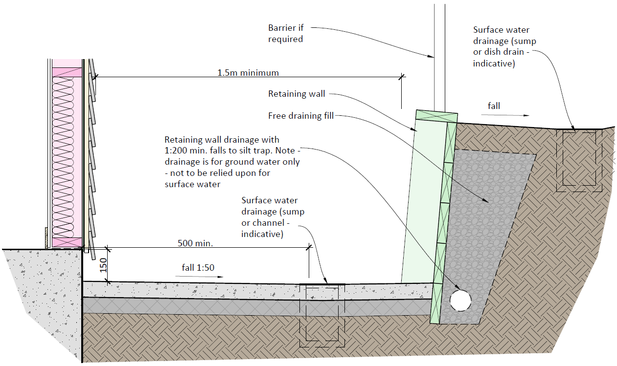
Retaining walls are to generally be configured as per Figure 5-1 below, so that:
5.2.1 They are separated from the exterior wall of the building by a minimum horizontal
Act
distance of 1.5 metres.
5.2.2 The ground between the retaining wall and the building is paved with a minimum 1:50
fall away from the building, and with surface water drainage provisions as per Section 4.
5.2.3 They have free draining backfill and drainage.
5.2.4 Retained ground level at the top of the wall has a minimum 500mm width of cross-fall
to surface drainage.
Information
Official
the
under
Figure 5-1 Example of Retaining Wall as a Separate Structure
Released
Weathertightness Design Requirements
13
Retaining Walls
6 Concrete Slab on Grade
6.1 Prohibited Items
The following materials, installations and construction systems are not to be used:
Nibs formed out of concrete blockwork
‘U’ shaped three-sided proprietary threshold channels that are placed against the
slab edge. This is because they do not allow the slab edge to dry out and can cause
water to wick up between the slab edge and drain
(1982)
Threshold channels at the base of wall cladding, except where they are suitably
sheltered as per Clause 6.3.4 below
Act
6.2 Cladding Ground Separation
The following issues must be considered:
6.2.1 Where new buildings (and extensions and additions) are constructed with a concrete
floor slab, the preference is that the finished floor level should be set above the
finished level of adjacent paved ground by a minimum of 150mm (or 100mm for brick
veneer) as per E2/AS1 to minimise the need for threshold channels or concrete nibs.
6.2.2 In situations where the height differences in Clause 6.2.1 are not provided, concrete
Information
nibs are to be used to position the bottom plates of timber framed exterior walls a
minimum of 150mm (or 100mm for brick veneer) above the adjacent paved ground.
6.2.3 It is acknowledged that due to accessibility, fire egress and the requirements of the
Designing Schools in New Zealand (DSNZ) document for flexible learning spaces,
threshold channels will be required at exterior doorways to achieve cladding separation
Official
from external ground (unless permeable slatted decks are used externally).
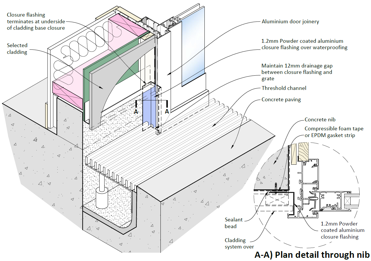
6.3 Threshold Channel Usage
the
6.3.1 With exception of exterior doorways, threshold channels must be used sparingly by the
Architect / Designer as they require sumps, drainage connections and ongoing
maintenance.
6.3.2 In order to protect interior spaces at external doorways, designers must take into
under
account the local conditions and exposure to wind driven rain to ensure compliance
with NZBC Clause E2.
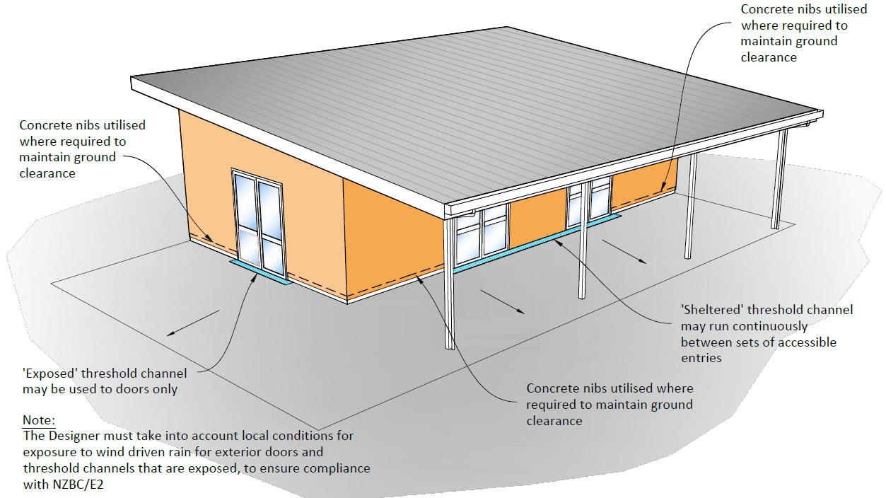
6.3.3 Threshold channels are primarily used to achieve cladding ground separation at exterior
doorway locations. Threshold channels with suitable shelter may also be continued
between a set of entrance doorways that are close to each other and along the same
external wall face as shown in Figure 6-2 below.
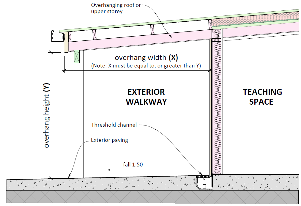
6.3.4 Suitable shelter is defined as a covered veranda, overhanging upper storey or recessed
Released
doorway that provides a horizontal overhang width which is equal to, or greater than
the vertical overhang height between exterior paving and soffit as shown in Figures 6-1
and 6-2 below.
Weathertightness Design Requirements
14
Concrete Slab on Grade
6.3.5 Threshold channels adjacent to exterior walls (in between exterior doorways) are an
alternative solution to NZBC Clause E2. Building Consent Authorities are expected to
require proof of compliance as part of the consenting process. This is the responsibility
of the Designer.
6.3.6 For exposed situations where suitable shelter (as defined in 6.3.4 above) is not
provided, threshold channels must be limited to use at external doorway locations only
to prevent moist air being drawn up the cladding cavity – refer to Figure 6-2 below.
(1982)
Act
Information
Figure 6-1 Suitable Shelter for a Threshold Channel
Official
the
under
Released
Figure 6-2 Example of Sheltered and Exposed Threshold Channels
Weathertightness Design Requirements
15
Concrete Slab on Grade
A summary of threshold channel usage is provided in Figure 6-3 below:
Threshold channels at
Threshold channels at
sheltered locations
exposed locations
(positioned under a wide soffit or
(not positioned under a wide soffit or
overhang as per 6.3.4)
overhang as per 6.3.4)
Can be used at accessible
doorways and also in between
Can only be used at exterior
(1982)
doorways along same wall
doorways
face
(refer Figures 6-2 & 6-7)
(refer Figures 6-1 & 6-2)
Act
The bottom edge of wall
Threshold channel must not
cladding must either be 50mm
run alongside external walls
above the threshold channel
and are limted to exterior
grate as Figure 6-4 or
doorways as shown in Figure
alternatively detailed as
6-2
Figures 6-5 or 6-6
Follow the detailed
Follow the detailed
requirements in Section 6.4
requirements in Section 6.4
Information
below
below
Figure 6-3 Summary Chart for Threshold Channel Usage
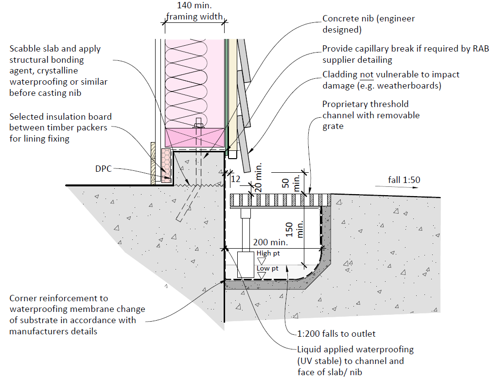
6.4 Threshold Channel Details
Official
In all cases where threshold channels are used, the following requirements must be met (refer
to Figures 6-4 to 6-7 below):
6.4.1 The threshold channel must be designed as “dry in service” – i.e. the adjacent paving
the
must flow away from the channel at a minimum slope of 1:50 and not into it, and it is
designed so that no water ponds in the channel (note: 1:50 paving falls are an
Alternative Solution to NZBC Clause E2).
6.4.2 The foundation & slab edge must be waterproofed with a liquid applied UV stable
under
membrane.
6.4.3 The channel must be laid with minimum 1:200 falls to a sump connected to the
stormwater system. This can include rain gardens where these are designed by a Civil
Engineer.
6.4.4 Channel drain outlet spacing:
where the threshold channel is suitably sheltered as per Clause 6.3.4, outlets are to
Released be provided at maximum 7400mm centres (this aligns with BRANZ
recommendations)
where the threshold channel is not suitably sheltered, outlets are to be provided at
maximum 3700mm centres
Weathertightness Design Requirements
16
Concrete Slab on Grade
6.4.5 The channel grate must be easily removable by school maintenance staff to allow
regular cleaning, with consideration to preventing removal or vandalism by others if
this is an anticipated issue.
6.4.6 The minimum clear internal width of the threshold channel is 200mm with a clear width
of grating of 150mm.
6.4.7 Threshold channel minimum depth must be 150mm minimum at the high point of fall.
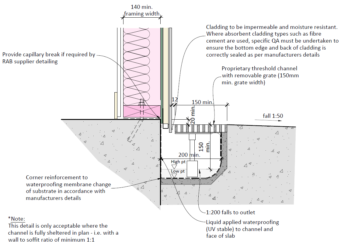
6.4.8 The bottom edge of cladding must be either:
A minimum of 50mm above the threshold channel grate with use of a nib wall to (1982)
achieve this (see Figure 6-4), or
Extended below the level of the threshold channel grate top, with the bottom edge
of the cladding treated to be impervious. However, this is only for situations where
Act
the threshold channel is suitably sheltered as per Clause 6.3.4 above (see Figure 6-6)
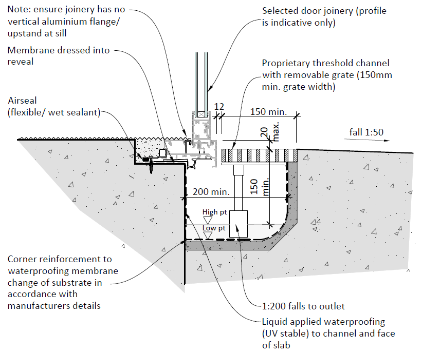
6.4.9 The top surface of the channel grate must be set no more than 20mm below the entry
threshold or internal finished floor level to meet NZBC and NZS4121 accessibility
requirements (see Figure 6-7).
6.4.10 Three-sided pre-formed channel systems are prohibited – the required solution are
systems specifically designed for level thresholds to building perimeters, of which there
are a number available in the market.
Information
Official
the
under
Released
Figure 6-4 Threshold Channel to Cladding
Weathertightness Design Requirements
17
Concrete Slab on Grade
(1982)
Act
Information
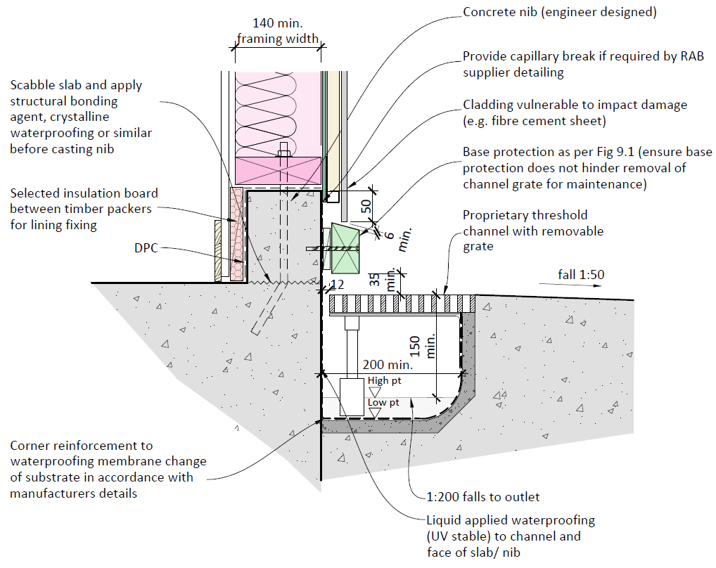
Figure 6-5 Threshold Channel to Cladding (with Cladding Base Protection)
Official
the
under
Released
Figure 6-6 Threshold Channel to Cladding (alternative detail for sheltered locations)
Weathertightness Design Requirements
18
Concrete Slab on Grade
(1982)
Act
Figure 6-7 Threshold Channel to Joinery Sill
Information
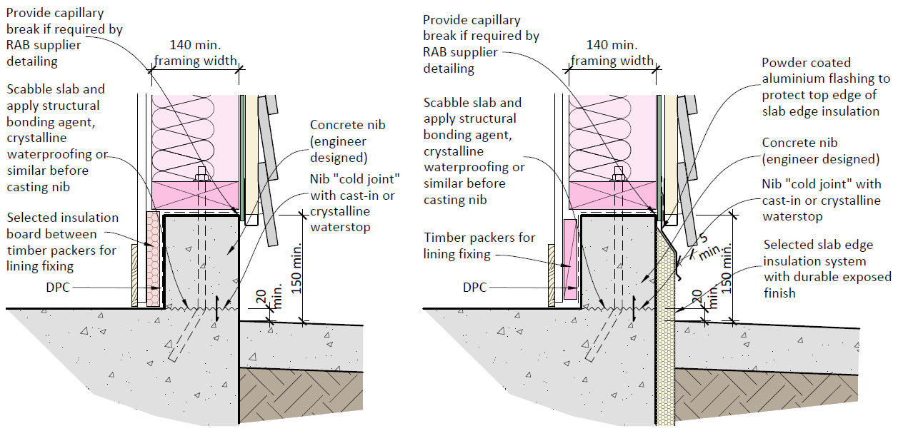
6.5 Concrete Nibs
Concrete nibs can be used to maintain cladding clearance to external ground level in limited
locations where it is not practicable to apply a 150mm (or 100mm for brick veneer) step
between finished floor level and adjacent outdoor paving as per Clause 6.2.1 above.
Official
Where concrete nibs are utilised, the following points must be incorporated:
6.5.1 They must be designed by a Structural Engineer.
the
6.5.2 They must have a minimum width of 110mm to allow for necessary construction
tolerances, capillary breaks and avoidance of cold bridging to the lining. Depending on
the type of rigid air barrier
product used, there may be a requirement for a separation
between the face of concrete and the back of the rigid air barrier
(see Figure 6-8
below).
under
6.5.3 Timber wall framing connected to the nib must have a minimum width of 140mm (see
Figure 6-8 below).
6.5.4 The external paving must be set to a maximum of 20mm below the internal floor level
to elevate the ‘cold joint’ above ground level (see Figure 6-8 below).
6.5.5 Where the nib is cast in a separate pour on top of the main floor slab, a waterstop must
be provided in the form of either crystalline waterproofing, a seal that swells on contact
Released
with water or a uPVC cast-in flashing. Surface painted waterproofing membranes to the
front of the nib are not effective in waterproofing the cold joint as the y are prone to
damage through movement, impact, or “blowing out” as construction moisture
dissipates from the nib (see Figure 6-8 below).
Weathertightness Design Requirements
19
Concrete Slab on Grade
6.5.6 Where there are steel posts or columns in the external wall, ensure these are located so
that the nib has a continuous external face for its complete length.
6.5.7 Where the concrete nib abuts door or full height window openings, provide detail s of
the nib and door frame junction at low level (below cladding). One indicative solution is
shown in Figure 6-9 below.
6.5.8 In the South Island and Central Plateau (Climate Zone 3), insulation must be provided,
either internally or externally, to address thermal bridging issues created by the nib and
the potential for condensation (see Figure 6-8 below). The Designer should also
determine on a project specific basis whether this is required for projects in Climate (1982)
Zones 1 and 2.
6.5.9 Where used, external insulation must be suitably protected from impact damage with
Act
an applied elastomeric plaster, cement render or other form of durable finish.
Information
Official
the
Figure 6-8 Concrete Nib Examples
Other options for concrete nibs include:
under
6.5.10 Forming the nib monolithically in the same pour as the main floor slab to eliminate the
cold joint and negate the need for waterstops.
6.5.11 Forming the nib in the same pour as the foundation and not the floor slab. As with
6.5.10 above, this can negate the need for waterstops.
6.5.12 Considering the use of insulation to the internal face of the nib to help address
potential thermal bridging issues.
Released
Weathertightness Design Requirements
20
Concrete Slab on Grade
(1982)
Act
Information
Figure 6-9 Example of
Concrete Nib to Door Frame Junction
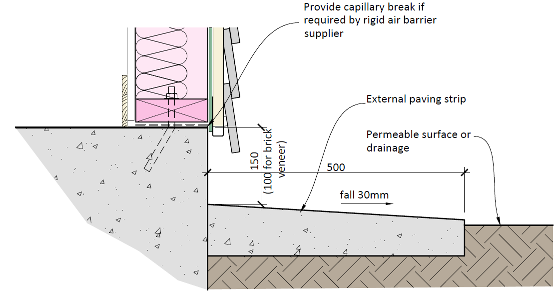
6.6 External Paving Strips
The total building perimeter including landscaped areas, must have a minimum 500mm wide
Official
strip of permanent paving set 150mm below internal finished floor level (or 100mm for brick
veneer) with 30mm fall away from the building into permeable surfaces (e.g. gardens or lawn)
or drainage systems as shown in Figure 6-10 below.
the
under
Released
Figure 6-10 External Paving Strip
Weathertightness Design Requirements
21
Concrete Slab on Grade
7 Suspended Timber Floors
7.1 Prohibited Items
The following materials, installations and construction systems are not to be used:
Particleboard flooring to wet areas (e.g. toilets, bathrooms and kitchens)
Untreated plywood to wet areas (e.g. toilets, bathrooms and kitchens)
7.2 Sub-floor Areas
(1982)
Where the ground floor is supported on piles:
7.2.1 Sub-floor ground must be overlaid with minimum 250 micron thick polythene sheets
Act
with all joints lapped and taped.
7.2.2 Polythene sheets must be fitted tight around, and be taped to piles. Where perimeter
walls are present, polythene sheets must also be fitted tight to, and taped to walls.
7.2.3 To permit visual inspection of all sub-floor areas:
Secure access doors or hatches are to be provided within the sub-floor external wall
Joists must be a minimum of 450mm above ground level
All piles (whether concrete or timber) must be a minimum of 300mm above ground
level
Information
7.2.4 Where there is a need for sub-floor ground to be excavated or set below adjacent
ground levels, impervious retaining walls are to be provided. Such retaining walls are
limited to no more than two sides of the building subfloor area to ensure adequate
drainage and access.
Official
7.2.5 Sub-floor areas must be designed to prevent any surface water flowing under the
building. In all cases, sub-floor ground must be graded to prevent water ponding.
7.2.6 Provide subfloor ventilation in accordance with NZS3604:2011 Clause 6.14
Prevention of
the
Dampness.
7.2.7 Vents in subfloor foundation walls must be vandal resistant and vermin-proofed with
care taken to ensure that the required free-ventilation area is achieved.
under
7.2.8 Vents must be evenly distributed to all external sub-floor walls, and be provided on at
least two sides of the subfloor space to ensure cross-flow ventilation.
7.3 Slatted Decks
The following requirements apply:
7.3.1 Where a slatted deck (i.e. rain permeable) is positioned adjacent to a suspended floor,
provide a sub-floor wall to separate it from the subfloor area to prevent dampness from
Released
below the deck entering the building sub-floor area.
Weathertightness Design Requirements
22
Suspended Timber Floors
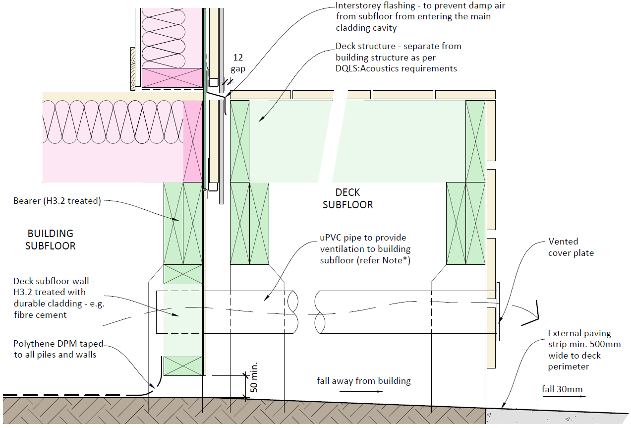
7.3.2 Where decks are present on more than one side of a building, uPVC pipe ducts must be
provided from the building subfloor to the outer edge of the deck as shown below in
Figure 7-1.
(1982)
Act
Information
Figure 7-1 Sub-floor Wall between Deck and Building
Official
7.4 Durability
the
Requirements include:
7.4.1 All fixings for sub-floor areas must be Type 304 stainless steel, unless there are specific
site circumstances that require the use of 316 stainless steel.
7.4.2 All sub-floor timber framing is to comply with NZBC Acceptable Solution B2/AS1.
under
Released
Weathertightness Design Requirements
23
Suspended Timber Floors
8 Exterior Wall Structure
8.1 Prohibited Items
The following materials, installations and construction systems are not to be used:
Curved walls
Walls that are not vertical
Concrete block structural walls to habitable / occupied spaces that are not over clad
Stack-bonded blockwork
(1982)
Honed face concrete blockwork
Expanding foam airseals to windows
Act
Galvanised steel fixings (nails, bolts, plates, etc.) in contact with timber treated with
copper-bearing preservatives
8.2 Timber and Steel Framed Walls
All timber and steel framed exterior walls are to be detailed to incorporate:
8.2.1 Exterior cladding to deflect moisture.
8.2.2 Drained cavity with top ventilation (refer to Section 9.4 and Figures 9-2 and 9-3).
8.2.3 Rigid air barrier to the outside face of all external wall framing members (refer to
Information
Section 9.5).
8.2.4 Flexible (wet sealant applied) air seals over backing rod to windows.
An exemption from the requirement to provide a cavity may be given for alterations to existing
buildings that have been constructed without a cavity, such as where windows are being
removed and in-filled to match an adjacent surface.
Official
8.3 Concrete Blockwork
the
The following requirements apply:
8.3.1 The base course of blockwork is to be set in a rebate at least 50mm below finished floor
level.
8.3.2 All blockwork must be laid and solid-filled under the supervision of a Brick and Block
under
laying Licensed Building Practitioner.
8.3.3 A cladding system fixed over a cavity is mandatory on the exterior face of structural
blockwork walls for all habitable / occupied spaces (e.g. excluding boiler rooms).
8.4 Concrete
Walls constructed of reinforced concrete (precast or in-situ) require specific design or peer
Released
review by a suitably qualified and experienced façade engineer and the provision of an
accompanying PS1 or PS2 producer statement.
The design must address the following issues:
Weathertightness Design Requirements
24
Exterior Wall Structure
8.4.1 Reliance on external waterproof coatings and sealants may not provide sufficient
redundancy for maintaining weathertightness over the life of the building.
8.4.2 Potential issues with internal moisture control and severe thermal bridging.
8.4.3 Maintenance requirements over the life of the building for:
Internal vapour control membranes, especially those with multiple services
penetrations, and
Exterior coating systems
Unintended structural cracking
(1982)
8.5 Timber Treatment and Fixings
Act
The following requirements apply:
8.5.1 In all situations where copper-bearing preservatives are used i.e. Chromated Copper
Arsenate (CCA), Copper Quat (CQ - previously Alkaline Copper Quaternary), Copper
Azole (CuAz) to achieve required treatment levels (i.e. H3.2 and above), fixings are to be
304 stainless steel (nails, staples, bolts etc.) unless there are specific site circumstances
that require the use of 316 stainless steel.
8.6 Junctions with Existing Buildings Information
The junction between the envelope of a new building and that of an existing, provides a
potential source of water ingress, particularly when design requirements such as seismic
junctions are involved. All such junctions are to be fully detailed in the detailed drawings.
Official
the
under
Released
Weathertightness Design Requirements
25
Exterior Wall Structure
9 Cladding Systems
9.1 Prohibited Items
The following materials, installations and construction systems are not to be used:
Direct-fixed cladding to timber and steel framed walls
Open jointed rain-screen cladding systems, unless a complete proprietary system is
used which comprises cladding panels, mounting rails and membrane applied over
the rigid air barrier
(1982)
Express jointed cladding systems which are reliant on sealant to form the cladding
panel joints
Act
H3.1 LOSP treated plywood cladding
H3.2 treated plywood cladding, unless primed and painted (with an oil based primer,
oil based undercoat and acrylic/ water based top coat system in mid to light colour
range)
Stain or oil-finished cladding
Monolithic cladding
EIFS cladding
Brick slips or adhesive fixed tiles applied to a substrate
Honed masonry veneer
Information
Cladding types within 2m of finished ground levels:
o fibre-cement cladding less than 8mm thick (depth at grooves not counted)
o uPVC systems
Cladding fixed over a cavity, and also used as wall bracing
Metal cladding on walls under eaves where the cladding cannot be easily washed down
Official
through hand-held equipment from ground level
Supporting struts under eaves and overhangs which penetrate cladding
the
9.2 Protection at Ground Level
Cladding within 2m of finished ground floor level is to be selected to withstand impact
damage.
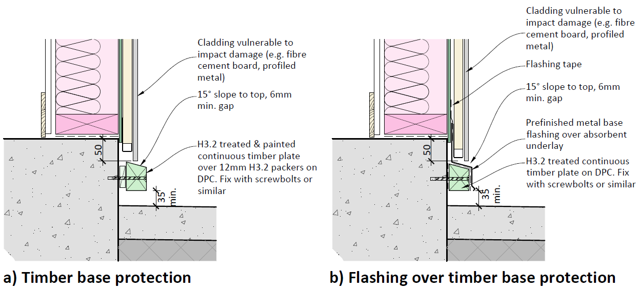
9.2.1 All ground floor cladding that is vulnerable to impact damage must be provided with
under
bottom-edge protection of timber or metal as shown in Figure 9-1 below. Vulnerable
cladding types include:
Fibre cement board 9mm to 15mm thickness (depth at grooves not counted)
Profiled metal cladding
Released
Weathertightness Design Requirements
26
Cladding Systems
(1982)
Act
Figure 9-1 Cladding Base Protection Options
9.3 Protection at Wall Corners
Cladding systems at corner locations that are vulnerable to impact damage must have suitable
exterior corner trim protection applied to withstand impact damage.
9.4 Cavity Construction - Timber and Steel Framed Walls
Information
9.4.1 Cavity construction must be used for all new buildings as well as extensions and
additions that create new footprint.
9.4.2 For existing buildings where the wall cladding has reached the end of its serviceable life,
the following requirements apply:
Official
Where there has been satisfactory in-service performance with no weathertightness
failures, and existing exterior joinery is to be retained, the cavity may be omitted if
this is permitted by E2/AS1
the
Where there has been satisfactory in-service performance with no weathertightness
failures, and existing exterior joinery is to be replaced, cavity construction must be
used
Where there has been unsatisfactory in-service performance, and irrespective of
whether existing exterior joinery is to be retained, cavity construction must be used
under
9.4.3 Cavities may be continuous for a maximum of two storeys in height (subject to cladding
supplier and E2/AS1 limitations).
9.4.4 For buildings with multiple fire compartmentation cells, a check must be made to
determine whether the cavity needs to be fire-stopped between floor levels or
separating walls. Such fire stopping details must be designed in such a way that they do
not inhibit cavity drainage.
Released
9.4.5 For cavity systems to fire rated walls, a check must be made to determine whether non-
combustible cavity battens are required.
Weathertightness Design Requirements
27
Cladding Systems
9.4.6 Cavities are to be:
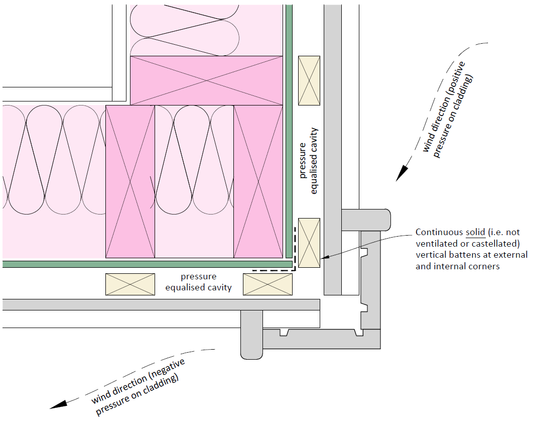
Compartmentalised at external and internal corners to provide separation from
cavities on adjoining wall faces to avoid undue wind pressure differentials and to
allow pressure equalisation / moderation to occur – refer to Figure 9-2
Separated from roof and subfloor areas to allow pressure equalisation / moderation
to occur and to avoid transfer of moisture from the ground - refer to Figures 7-1 and
9-3
Drained to allow any moisture that penetrates the cladding to escape
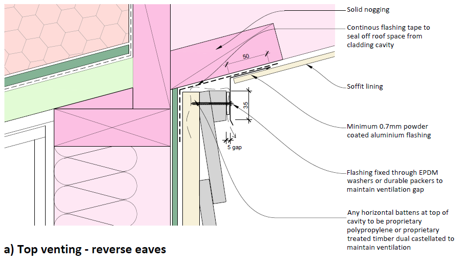
Top vented on buildings up to two storeys in height to assist drying by allowing air (1982)
movement to aid evaporation - refer to Figure 9-3 (the Ministry has obtained
Determination 2013/046 to allow top-venting)
Provided with a method of draining at each floor level where a building exceeds two
Act
storeys in height unless otherwise recommended by the cladding manufacturer’s
requirements
Vermin-proofed by cavity closers with holes or slots to maintain drying and venting
to protect all framing voids and cavities
9.4.7 Cavity battens providing support for cladding fixed horizontally (e.g. bevel-back or
rusticated weatherboard), are to be:
H3.1 timber and fixed vertically
Installed to maintain the openness of the wall cavity (for drainage and ventilation)
Information
and positioned to support the cladding at the centres required by the manufacturer
9.4.8 Where claddings such as profiled metal sheet, vertical weatherboards etc. are fixed
vertically and horizontal battens are required, the battens must allow free drainage and
ventilation. Only proprietary products such as extruded proprietary polypropylene
battens or treated proprietary dual castellation battens (where they form part of a
Official
tested cladding system) may be used.
9.4.9 Cavity spacers providing intermittent support for fixings or wall penetrations are to be
short lengths, and set to a slight fall (5° minimum from horizontal) to allow drainage of
the
any moisture from the top.
9.4.10 Rain-screen cladding systems utilising galvanised steel or aluminium rails or top hats to
form a cavity system may be used provided they are supported with proof of NZBC
compliance such as a BRANZ Appraisal or NZS4284 testing.
under
Released
Weathertightness Design Requirements
28
Cladding Systems
(1982)
Act
Information
Figure 9-2 Cavity Compartmentalisation at Corner
Official
the
under
Released
Weathertightness Design Requirements
29
Cladding Systems
(1982)
Act
Information
Official
the
under
Figure 9-3 Top Venting
9.5 Rigid Air Barriers - Timber and Steel Framed Walls
9.5.1 Rigid air barriers are to be used for all buildings.
Released
9.5.2 Rigid air barriers are to be tested and BRANZ appraised proprietary fully taped systems
based on materials or products such as:
Fibre cement (minimum 6mm thick)
H3.2 treated plywood (minimum 7mm thick) with stainless steel fixings
Weathertightness Design Requirements
30
Cladding Systems
Water resistant fibreglass reinforced gypsum
Oriented Strandboard (OSB) with laminated wall underlay
Cross Laminated Timber (CLT) (when used as a structural wall system) with BRANZ
Appraised self-adhesive underlay
9.5.3 In areas of high seismicity (as defined by the Building Act 2004), fibre cement rigid air
barrier must be overlaid with a flexible building-wrap or BRANZ appraised self-adhesive
layer to ensure the weathertightness integrity is maintained if the rigid air barrier is
damaged as a result of a seismic event (where the rigid air barrier cannot be readily
inspected for damage).
(1982)
9.5.4 Where the rigid air barrier is overlaid with a wall underlay it is the responsibility of the
Designer to confirm compatibility, fixing and warranty requirements with both the rigid
Act
air barrier and underlay suppliers.
9.6 Metal Wall Cladding
Profiled metal cladding is a commonly used and affordable cladding system that is widely used
for school buildings. The cladding is appropriate for simple walls with few penetrations or
openings, but inexperienced applicators can struggle with complex junctions, especially when
internal and external corners coincide with window openings.
The following requirements apply:
Information
9.6.1 Except where more stringent requirements are given in this document, metal wall
cladding must be detailed and installed to comply with the NZ Metal Roof and Wall
Cladding Code of Practice Version 3, or with the manufacturer’s installation
specification and details where proprietary tested systems are used.
9.6.2 Consideration should be given to avoiding the use of profiled metal cladding for
Official
complex wall elevations with multiple junctions, openings and penetrations where
complex flashings are required.
9.6.3 Ensure all surfaces of profiled metal cladding systems are exposed for natural washing
the
by rainwater, or can be easily washed down through hand-held equipment from ground
level.
9.6.4 Provide bottom edge protection where required by Section 9.2.
under
9.7 Masonry Veneer Cladding
Reference should be made to the Ministry’s Structural and Geotechnical Requirements (SGR)
for guidance and limitations on usage.
When concrete masonry is used as a veneer, control joints are to be detailed and control joint
locations shown on the elevations.
9.8 Exposed Structural Elements
Released
In general, structural elements may only penetrate cladding where there is no other feasible
option. Projecting structural beams, outrigger elements and cantilevered joists for decks should
be avoided as these are all potential sources of water ingress.
Other key points include:
Weathertightness Design Requirements
31
Cladding Systems
9.8.1 External elements such as escape stairs and steel decks are best kept as free-standing
structures to avoid penetrations.
9.8.2 Sun-shade structures should keep cladding penetrations to a minimum and use regular
shaped profiles that keep flashing details simple. Circular hollow section (CHS),
rectangular hollow section (RHS) or steel fin profiles are easier to flash against in
comparison to universal beam (UB) or Parallel Flange Channel (PFC) sections.
9.8.3 Structural beams or outriggers should be enclosed in the soffit or otherwise suitably
enclosed so that cladding penetrations are not necessary.
(1982)
9.8.4 Full 3D detailing must be provided for all penetration situations through the external
envelope.
Act
Information
Official
the
under
Released
Weathertightness Design Requirements
32
Cladding Systems
10 Roof
10.1 Prohibited Items
The following materials, installations and construction systems are not to be used:
Low pitched roofs (see Clauses 10.2.4 and 10.8.7 below)
Curved metal roofs
Parapets (including solid framed deck balustrades)
Liquid applied membranes to roofs
(1982)
Butyl Rubber and EPDM Membranes
Reflective paint systems over torch-on roofing membranes
Act
Pressed metal tiles
Reliance on sealant at joints / junctions for weathertightness
Internal gutters and scuppers
PVC spouting systems (unless matching the existing for an extension or addition)
Leaf gutter mesh
Overhangs where the underside of metal roofing is exposed
Oiled or stain finished treatments for plywood or timber soffits
Services plant, such as heat pump outdoor units (with exception of solar panels
and/or fan cowls for extraction and supply air), are not to be located on roofs
Information
10.2 Metal Roofing - General
Climate change has resulted in more intensive rainfall and as a consequence, a conservative
approach to roof design and rainwater collection systems is required. Other considerations
include the use of warm roofs as the Ministry’s preferred roof type for new school buildings as
Official
covered in Section 10.16 below.
The following requirements apply:
the
10.2.1 With reference to E1/AS1 and the NZ Metal Roof and Wall Cladding Code of Practice
Version 3.0, use a minimum rainfall intensity of 100mm/hr for the design of collection
and disposal systems for roof areas.
10.2.2 Metal-clad roofs are to be detailed and installed to comply with NZ Metal Roof and Wall
Cladding Code of Practice Version 3.0 except where more stringent requirements are
under
given in this document.
10.2.3 The minimum Base Metal Thickness (BMT) for all steel roofs must be 0.55 mm.
10.2.4 The minimum roof pitch for new buildings must be:
Trough and trapezoidal section profile metal roofing - 5 degrees
Corrugated profile metal roofing - 12 degrees
10.2.5 For existing buildings where the roof cladding system has reached the end of its
Released
serviceable life, the following requirements apply:
Where there has been satisfactory in-service performance with no weathertightness
failures, there is no requirement to re-pitch the roof providing it can be
Weathertightness Design Requirements
33
Roof
demonstrated that the new roof cladding will continue to be code compliant for the
remaining life of the building
Where there has been unsatisfactory in-service performance, the minimum roof
pitches identified in E2/ AS1 or the NZ Metal Roof and Wall Cladding Code of
Practice Version 3.0 must be achieved
10.2.6 The preferred maximum roof pitch is 25 degrees for safer maintenance access.
However, a steeper pitch may be required to match existing adjacent buildings (e.g.
heritage considerations) or when replacing existing roofs.
(1982)
10.3 Metal Roofing - Underlay
Roof underlay must:
Act
10.3.1 Have a current BRANZ Appraisal.
10.3.2 Be fully supported (mesh must comply with Safety Mesh Standard AS/NZS 4389:1996).
Where underlay is stated by the manufacturer to be ‘self-supporting’, mesh must still
be provided regardless of purlin spacing.
10.3.3 Be separated from insulation by a 20mm air gap (except where proprietary warm roof
systems with moisture resistant board insulation are used).
10.3.4 Be water resistant, absorptive (hydrophobic), permeable synthetic non-woven
Information
(polymeric) type complying with Table 23 E2/AS1.
10.3.5 Have side and end laps of 150mm (or as per the manufacturer’s requirements,
whichever is greater).
10.3.6 Be laid horizontally (except on roofs > 8 degrees where it may be laid vertically ).
10.3.7 Have all penetrations, junctions, and laps (where laid vertically as per Clause 10.3.6)
Official
sealed with a compatible designer / manufacturer approved window sealing tape.
the
10.4 Metal Roofing - Penetrations
The following requirements apply:
10.4.1 Penetrations are to be kept to a minimum (leaks are often associated with roof
penetrations). Roof mounted plant (e.g. air conditioning units) are not permitted –
under
these should be ground mounted.
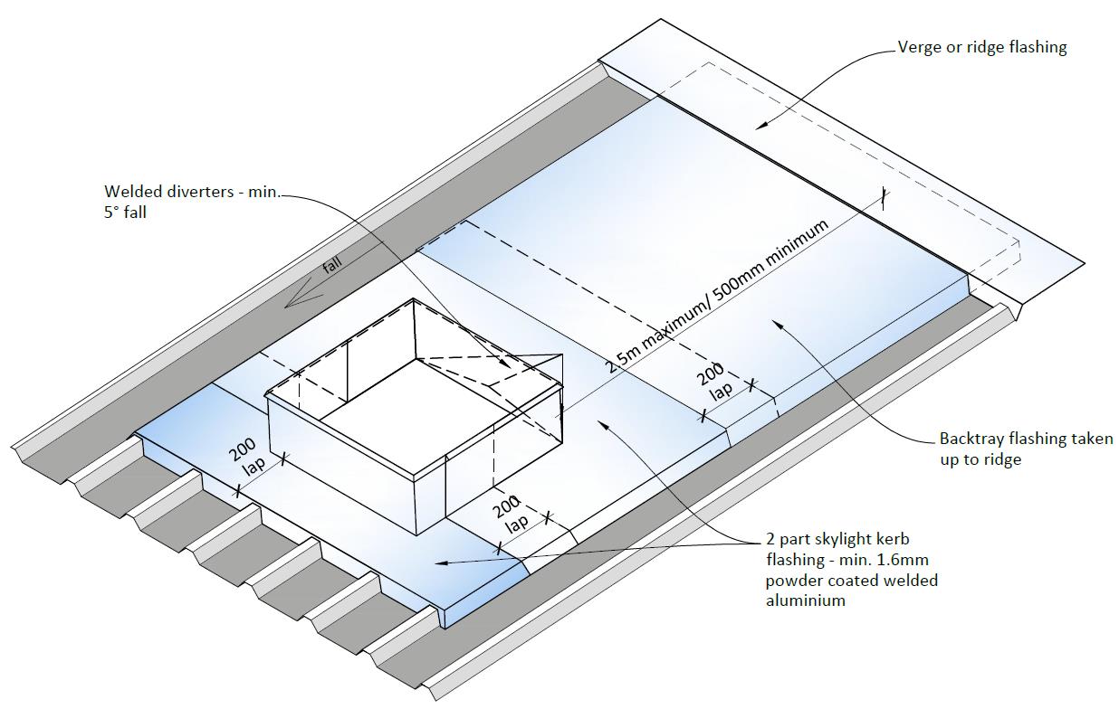
10.4.2 The top face of large roof penetrations (e.g. skylights, vent cowls) are to be located
within 2.5m of the ridgeline to minimise the length of back flashing needed from the
penetration to the ridge above it. Refer also to the Roofing Code of Practice which
limits watershed flashings to a maximum width of 1200mm.
10.4.3 Square or box form penetrations must be detailed with a welded ‘cricket’ diverter
flashing formed from 1.6mm minimum thickness welded aluminium and over-flashed to
Released
the ridge. Alternatively, the penetration can be turned in plan through 45 degrees.
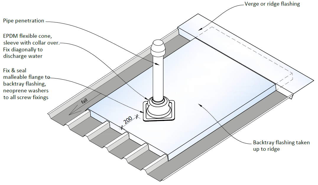
10.4.4 Small penetrations (e.g. pipes) are to be directed within the roof structure to emerge at
sensible locations (e.g. well clear of other flashings or roof junctions to avoid clashes) .
Penetrations greater than 300 x 300mm must be fully supported all round.
Weathertightness Design Requirements
34
Roof
10.4.5 All roof penetrations and roof mounted fixings (e.g. sky aerials, fall arrest system hooks
etc.) must be detailed in the drawing set. Fall arrest systems must be designed by a
suitably qualified person.
Refer to Figures 10-1 and 10-2 below for a typical skylight flashing and vent-pipe detail.
(1982)
Act
Information
Figure 10-1 Typical Skylight Flashing
Official
the
under
Released
Figure 10-2 Typical Roof Pipe Penetration
Weathertightness Design Requirements
35
Roof
 10.5 Metal Roofing - Flashings
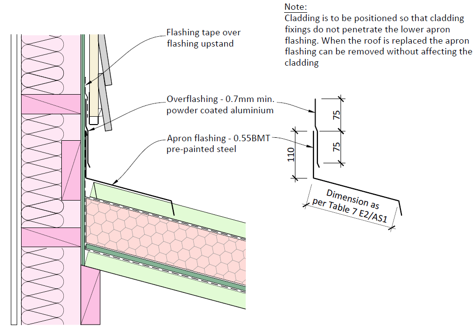
10.5.1 Flashing materials are to be generally as per the Table 1 below. A typical two part apron
flashing is also shown in Figure 10-3 below.
Flashing type
Example
Material
Standard roof flashings which are
Same material as the roof (e.g.
rain washed and can be easily
Ridge, barge, verge, eaves
0.55mm pre-painted steel)
replaced when the roof is replaced
Roof flashings which cannot be
0.9mm powder coated (1982)
replaced without removing
Apron, parallel gutter
aluminium, or use two part
adjacent cladding, or are in
flashing as per Figure 10-3
sheltered locations
Act
Compound flashing (the assembly
1.6mm or 2mm powder coated
Complex roof junctions
involves more than two planes), such as:
Intersection of two opposing barges
fully welded aluminium
Skylight cricket/ diverter flashing
Cladding flashings for pre-painted
Same material as the cladding
Corner flashings, window flashings
steel cladding
(e.g. 0.55mm pre-painted steel)
Minimum 0.7mm powder coated
Cladding flashings for other
Corner flashings, window flashings, soffit
aluminium, or uPVC, or as per
cladding types (weatherboard,
flashings
suppliers proprietary tested
fibre cement etc.)
system details
Information
Table 1 Flashing Materials and Thicknesses
Official
the
under
Released
Figure 10-3 Typical
Two Part Apron Flashing
Weathertightness Design Requirements
36
Roof
10.5.2 Complex junctions are defined when the flashing assembly involves three planes (e.g.
vertical, horizontal and sloping) that are joined together to form a continuous
watertight barrier.
10.5.3 Flashings to complex junctions must be formed of powder coated aluminium with all
joints fully welded (refer also to Table 1 above for thickness).
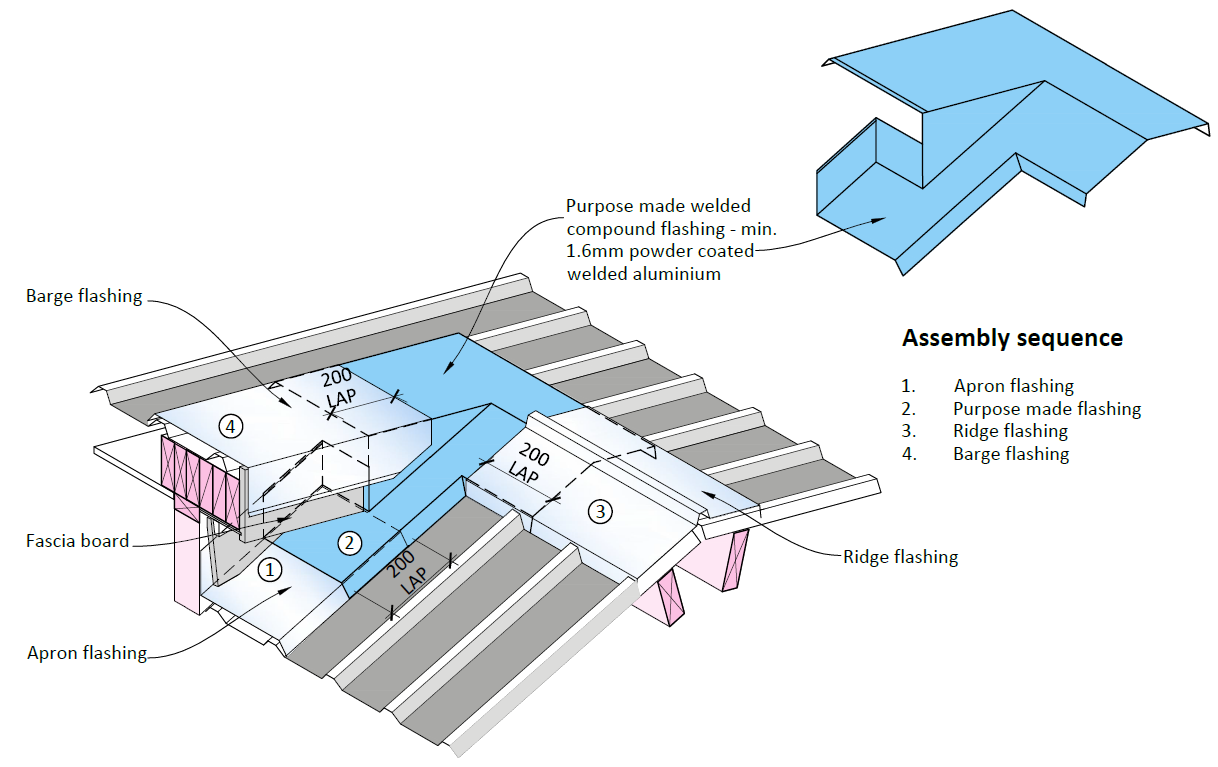
10.5.4 All complex roof junctions are to be fully detailed in three dimensions. Refer to Figures
10-4, 10-6 and 10-7 below. These are examples only; bespoke details are required to
suit the specific requirements of each individual project.
(1982)
Act
Information
Official
the
Figure 10-4 Example of
3D junction - Roof to Barge
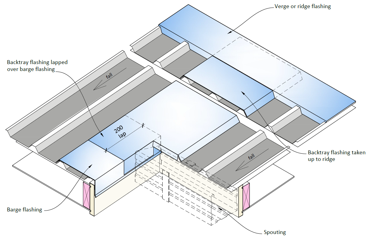
10.5.5 Where a barge flashing is terminated partway up a roof, the barge flashing termination
is required to be over flashed with a back tray flashing up to the ridge, verge or apron
under
as shown below in Figure 10-5.
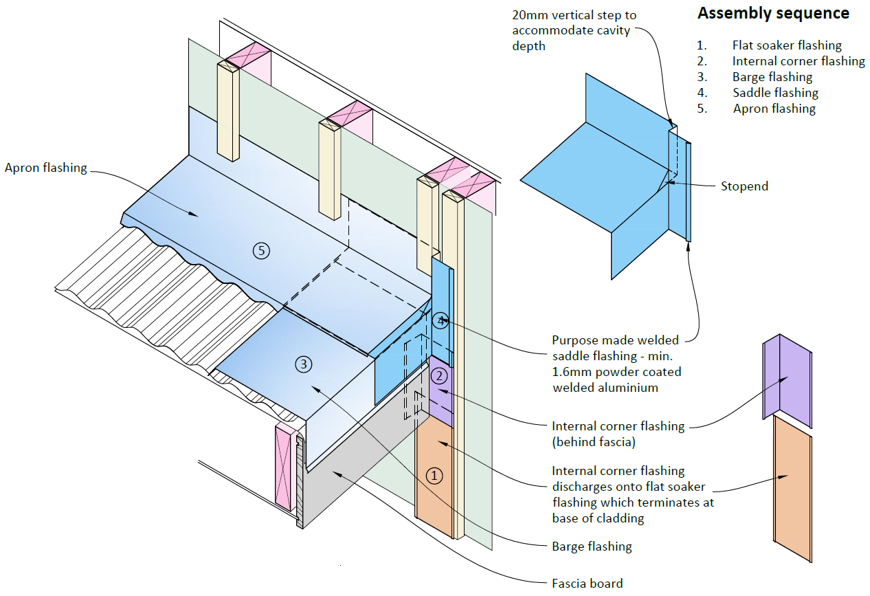
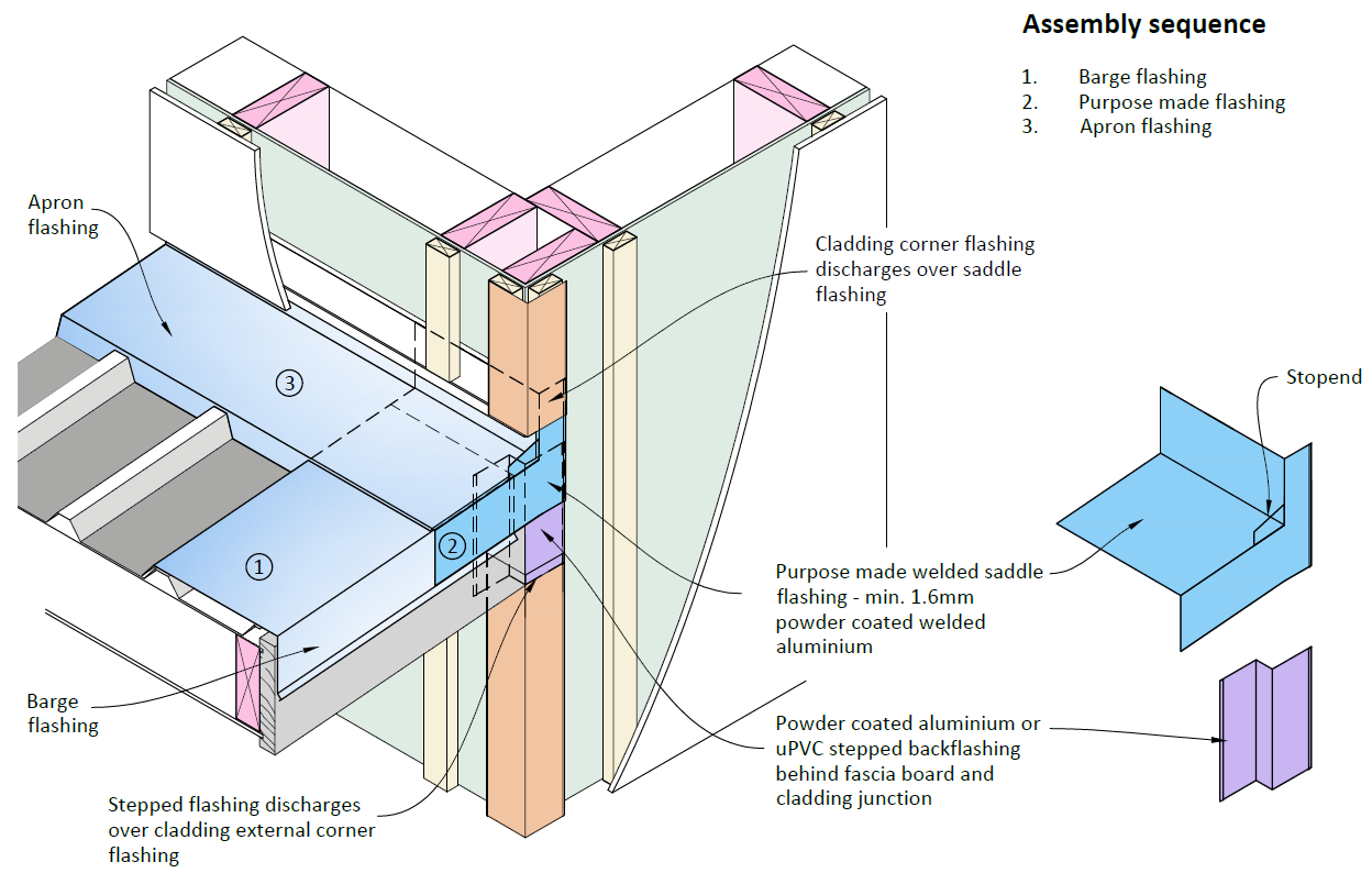
10.5.6 A barge flashing at wall and corner wall situations are shown in Figures 10-6 and 10-7
below.
Released
Weathertightness Design Requirements
37
Roof
(1982)
Act
Figure 10-5 Barge Termination Partway up a Roof
Information
Official
the
under
Figure 10-6 Example of
3D Junction - Barge Flashing to Wall
Released
Weathertightness Design Requirements
38
Roof
(1982)
Act
Figure 10-7 Example of
3D Junction - Barge Flashing at a Corner Wall
Information
10.6 Metal Roofing - Valley Gutters
10.6.1 Valley gutters must be designed in accordance with section 5-2-4 of NZ Metal Roof and
Wall Cladding Code of Practice Version 3.0.
10.7 Metal Roofing – Ventilation
Official
Careful consideration must be given by the Designer to roof space ventilation and prevention of
internal moisture issues in the roof space. In this regard, warm roofs are the Ministry’s preferred
the
roof type for new school buildings as covered in Section 10.16 below.
The following requirements apply for ‘cold-roof’ situations:
10.7.1 Provide cross ventilation between the roof-space voids below the roofing substrate.
10.7.2 Roof space ventilation must be provided to disperse internal moisture and prevent
under
condensation within the roof space. Ventilation options include proprietary ventilation
batten systems (with vents at the eaves and ridge) or soffit vents.
10.7.3 Vents must be designed to ensure the roof remains water-tight.
10.8 Membrane Roofing - General
Projects which incorporate membrane roofing require precise detailing and an increased level of
Released
attendance and observation by the Designer at the time the substrate is fitted and the
membrane installed. The designer must also include a specific QA programme within the design
documentation.
10.8.1 Where membranes are used they are to have:
Weathertightness Design Requirements
39
Roof
Current BRANZ Appraisal or Codemark Certificate
Minimum 15 year material warranty
Minimum 5 year installation warranty
10.8.2 Membranes types are to be either:
Two layer fully-bonded torch-applied reinforced modified bitumen membranes
with mineral chip finish, installed in accordance with the Code of Practice for
Torch-on Membrane Systems for Roofs and Decks
Synthetic plastic sheet membranes with welded joints such as Thermoplastic Olefin
(TPO), Ketone Ethylene Ester (KEE) and PVC
(1982)
10.8.3 Membranes must be installed by applicators licensed or approved by the manufacturer.
10.8.4 Plywood, concrete or warm roof substrates are to be fully protected to maintain
Act
dryness and the required relative humidity levels (RH) as stipulated by the
manufacturer until the membrane is laid.
10.8.5 Internal gutters, scuppers and parapets are not permitted. Membrane roofs must
discharge to external spouting via a formed drip edge in accordance with the membrane
manufacturer’s requirements and details.
10.8.6 Contract documentation must use cross-sections primarily, with supplementary plans as
necessary, to show the levels of the high and low points of the substrate at all edges
and changes of plane. Work the levels back from the low point of membrane at the
Information
outlet.
10.8.7 Membrane roofs are to have:
Minimum number of sheet joints (laid parallel the direction of roof fall only)
Minimum pitch of 3 degrees
Official
10.9 Membrane Roofing – Ventilation
The following requirements apply for ‘cold-roof’ situations:
the
10.9.1 Provide cross ventilation between the roof-space voids below the membrane substrate.
10.9.2 Proprietary vapour vents from the voids at 1 / 40m2 of roof area (minimum vent area
400 mm2), or as per the manufacturer’s system requirements.
under
10.9.3 Vents must be designed to ensure roof remains water-tight.
10.9.4 Any resulting reduction in ‘R’ value of thermal insulation is to be taken into account.
10.9.5 Where ‘warm roof’ systems are used – refer to manufacturer’s requirements.
10.10 Translucent Roofing
Requirements for translucent sheeting are provided on the Ministry’s public webpage titled
Roofing materials for school buildings under the following filepath:
Released
https://education.govt.nz/school/property-and-transport/projects-and-design/design/design-
standards/materials/roofing-materials/
Weathertightness Design Requirements
40
Roof
10.11 Sarking
The following requirements apply:
10.11.1 Plywood used as sarking must have its thickness determined by span, with a minimum:
15mm under profiled metal roofs (or as per roofing manufacturer’s requirements)
17.5mm as substrate for membrane roofs
19mm as substrate for decks
10.11.2 Plywood used as sarking and other roof substrate applications such as valley boards,
must be H3.2 treated.
(1982)
10.12 Eaves
Act
Eaves are required to ensure that rainwater collection points (spouting, rain water heads and
downpipe spreaders) to the roof system are positioned away from the external face of the
building, so that in the event of a blockage or defect, water will ov erflow externally and away
from the building’s envelope.
Other key considerations for eaves include:
10.12.1 For single storeyed buildings, overhanging eaves provide useful protection to
windows/doors immediately underneath and help deflect rainwater away from ex ternal
walls.
Information
10.12.2 For multi-level buildings, they provide less benefit to lower floors, or to window or door
openings in a gable end wall or high end of a mono-pitch roof where the eave overhang
is some distance up from the head flashings.
10.12.3 They can be a means of providing solar shading to prevent direct sunlight from entering
the building during summer months (refer to the Ministry’s DQLS document on Thermal
Official
Comfort and Indoor Air Quality, and Lighting).
10.12.4 They can however compromise durability for metal wall cladding systems where they
hinder/prevent natural rain-washing of cladding directly below the eave overhang to
the
remove accumulation of airborne salts (refer also Section 3.3).
The following requirements apply:
10.12.5 All roof rainwater collection points (spouting, rain water heads and downpipe
under
spreaders) must be positioned at least 600mm from the external face of the building
directly below the roof, by provision of an eaves or veranda overhang.
10.12.6 Eaves should not be used over profiled metal walls cladding systems in situations where
the cladding cannot be easily washed down through hand-held equipment from ground
level.
10.12.7 For metal roofing in Wind Zones Very High and Extra High (NZS 3604), provide the eaves
flashing as shown in E2/AS1 Figure 45.
Released
10.12.8 Plywood used as soffits must be H3.2 treated and have a painted finish (oiled or stained
finishes are not permitted).
Weathertightness Design Requirements
41
Roof
10.13 Rainwater Head Overflows
10.13.1 Overflows are to be provided as an opening in the rainwater head and:
Cross-sectional area of overflow must be 1.5 times the area required for the outlet
Height must be set so that the overflow functions before water can enter the
structure, if the downpipe becomes blocked
10.13.2 Rainwater heads are recommended at the termination of a valley or parallel gutter or in
areas where high volumes of water are discharged from high level roofs (e.g. via
spreaders).
(1982)
10.14 Exterior Spouting
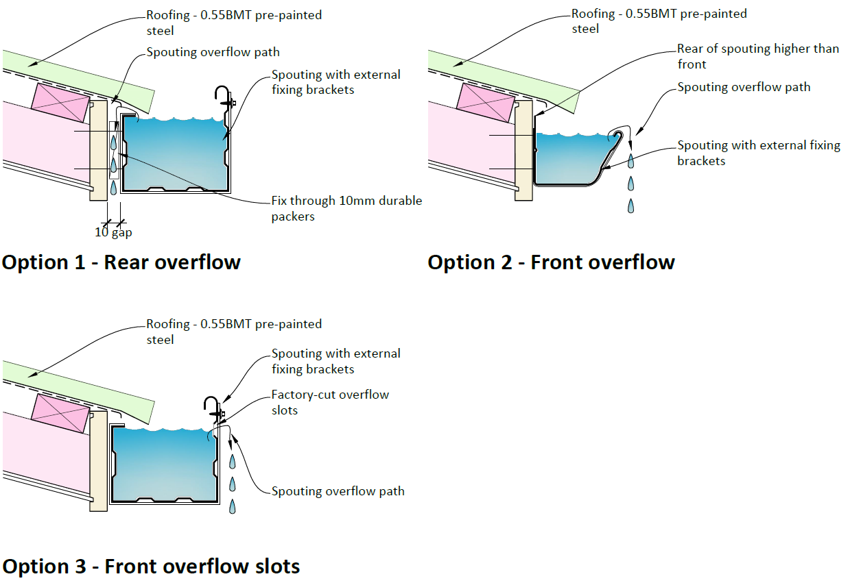
Exterior spouting of metal or PVC must be installed so that overflow provision is provided by one
Act
of the following options (refer Figure 10-8 below):
10.14.1 Rear Overflow (Option 1): minimum 10mm overflow gap between the rear of the
spouting and the fascia board or cladding.
10.14.2 Front Overflow (Option 2): spouting which has a front edge that is lower than the rear
edge; or
10.14.3 Front Overflow Slots (Option 3): metal spouting with factory cut overflow slots in the
front face (which are positioned lower than the rear edge of the spouting)
Information
To incorporate robustness and redundancy into the design of rainwater goods:
10.14.4 Gutter capacities are to be in accordance with NZ Metal Roof and Wall Cladding Code of
Practice Version 3.0 and oversized nominally.
10.14.5 Gutters must always have external brackets.
Official
the
under
Released
Weathertightness Design Requirements
42
Roof
(1982)
Act
Information
Figure 10-8 Spouting Overflow Options
10.15 Thermal Expansion
Official
Metal and plastic roofing is subject to thermal expansion and contraction due to cyclical changes
in local external temperatures. When thermal expansion movement is not consider ed and
accommodated in the design of metal roofs, flashings and spouting, damage and
the
weathertightness failure can occur due to the stresses of movement on fixings and metal sheet.
10.15.1 Expansion must be considered by the Designer, with specific flashing expansion details
to be provided as part of the Detailed Design set. Reliance on general drawing or
specification notes only is not acceptable.
under
10.15.2 Roofs, flashings and gutters with uninterrupted lengths of over 12m will require specific
design to accommodate thermal expansion.
10.15.3 Design for thermal expansion is to be in accordance with sections 7.3 and 8.9 of the NZ
Metal Roof and Wall Cladding Code of Practice Version 3.0.
10.16 Condensation and Thermal Bridging
Warm roofs are the preferred roof type for new school buildings to provide a more effective
Released
thermal envelope, help eliminate cold bridging and help avoid aggravated thermal bridging. Use
of warm roof systems can also assist with meeting the Ministry’s acoustics requirements for
control of rain-on-roof noise (refer to the current edition of Ministry’s Designing Quality
Learning Spaces – Acoustics document).
Weathertightness Design Requirements
43
Roof
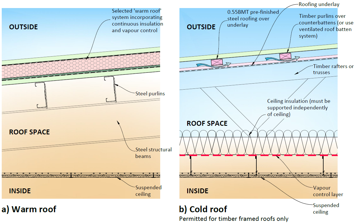
10.16.1 Where the roof structure is steel (i.e. steel rafters/ portals and/ or steel purlins), a
warm roof system must be used (see Figure 10-9 below).
10.16.2 Where there is a risk of aggravated thermal bridging occurring in the roof space, a
warm roof system must be used.
10.16.3 Cold roofs are permitted (but not preferred) for timber framed roof structures . If used,
careful consideration must be given by the Designer to roof space ventilation and
prevention of internal moisture issues in the roof space. See Figure 10-9, and also refer
to refer to Sections 10.7 and 10.9.
(1982)
Note: for an explanation of the causes of aggravated thermal bridging refer BRANZ Bulletin No.
572 titled: Aggravated Thermal Bridging Research.
Act
Information
Official
the
Figure 10-9 Warm Roof vs. Cold Roof Example
under
Released
Weathertightness Design Requirements
44
Roof
11 Exterior Joinery
11.1 Prohibited Items
The following materials, installations and construction systems are not to be used:
Circular windows (including curved window elements such as arched or curved
window heads)
Curtain wall glazing exceeding 2 storeys in height
Windows with raking jambs or sills (i.e. sills are to be horizontal and jambs vertical, (1982)
but heads may be either raked or horizontal)
Irregular shaped windows
Act
11.2 Recessed Windows
Recessed window detailing may only be used in the following situations:
11.2.1 For metal cladding as per the NZ Metal Roof and Wall Cladding Code of Practice
Version 3.0.
11.2.2 Where the recessed window details are part of a proprietary tested cladding system
(with a BRANZ Appraisal, CodeMark certificate or NZS4284 test report to support
compliance).
Information
Where recessed windows are used:
11.2.3 Full 3D details showing junctions of jamb/ sill flashings and head/ jamb flashings must
be provided.
11.2.4 All flashings must be mechanically secured and must not rely on sealant.
Official
the
under
Released
Weathertightness Design Requirements
45
Exterior Joinery
12 Balconies
12.1 Prohibited Items
The following materials, installations and construction systems are not to be used:
Construction using cantilevered timber joists
Cantilevered glass balustrades without a handrail
Balconies constructed over occupied internal spaces
Solid balustrades
(1982)
12.2 Upper Level Decks / Walkways/ walkways
Act
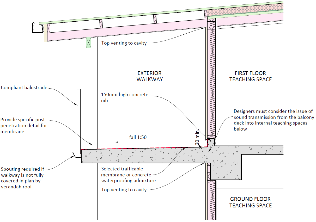
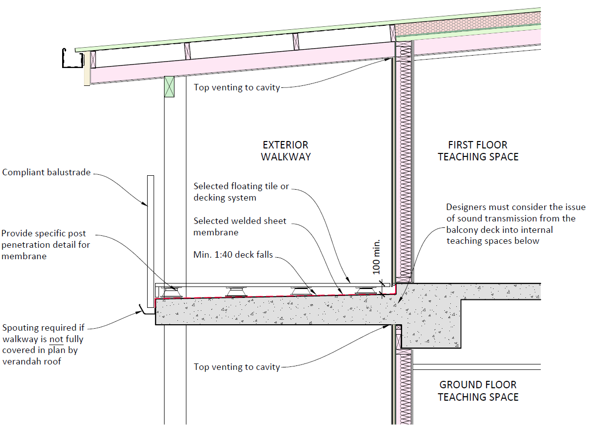
Where concrete decks or walkways are provided at first or second floor level as an integral
part of the primary upper floor slab the following requirements must be met (refer to Figures
12-1 and 12-2 below):
12.2.1 Concrete decks must be laid, either:
With 1:50 falls as the maximum cross-fall allowable for accessibility (however this is
an alternative solution to E2/AS1 for deck membrane falls and will require Building
Consent Authority and membrane supplier approval if a membrane is used), or
To E2/AS1 falls (1:40 minimum) with a floating tile or decking system over to meet
accessibility requirements and provide level access.
Information
12.2.2 Concrete decks must be waterproofed with either:
A trafficable welded sheet membrane
A non-trafficable welded sheet membrane (as per Section 10.8) with a floating tile or
deck system over
A proprietary concrete waterproofing treatment (such as a penetrating spray-on
Official
system, or admixture) with suitable proof of NZBC compliance for use on concrete
decks. Where such a system is used, attention must be paid to the design limitations
of the system (e.g. minimum required falls, maximum crack bridging ability,
the
maintenance requirements). Concrete deck construction must be detailed with
particular attention to address cold jointing between pour elements together with
mitigation of shrinkage cracking during the curing process
A proprietary trafficable liquid applied membrane system, provided that
under
maintenance and re-coating requirements are considered, agreed with the school
and incorporated into a maintenance schedule
12.2.3 Where a proprietary floating tile or decking system is to be used in high wind pressure
locations, an engineering check must be undertaken to prevent tiles or decking from
becoming dislodged.
12.2.4 Where a sheet waterproofing membrane is used, full detailing of penetrations and
junctions must be provided (e.g. veranda post penetrations, side fixed balustrade
Released
detailing, transitions to external stairs, membrane to building corner kick -out details
etc.).
12.2.5 Where concrete nibs are required to provide cladding clearance, these are to be
designed in accordance with Section 6.5.
Weathertightness Design Requirements
46
Balconies
12.2.6 Provision of threshold channels to accessible thresholds at suspended concrete floors
can be difficult to achieve from a structural engineering perspective. Where a threshold
channel with dimensions to comply with E2/AS1 cannot be achieved for practical
reasons, the architect / designer is to provide a bespoke solution for the drainage.
12.2.7 Where the deck or walkway is not fully covered in plan by a veranda roof, exterior
spouting to the edge of the walkway must be provided for collection of rainwater .
(1982)
Act
Information
Official
the
Figure 12-1 Waterproofing to Upper Decks – Trafficable Membrane or Waterproofing Admixture
under
Released
Weathertightness Design Requirements
47
Balconies
(1982)
Act
Information
Figure 12-2 Waterproofing to Upper Decks – Non-trafficable Membrane with Floating Deck/ Tiles
Official
the
under
Released
Weathertightness Design Requirements
48
Balconies
Appendix A: Glossary & References
Acceptable Solution
A non-mandatory means of complying with the Building Code. If a building owner chooses to
use an Acceptable Solution the BCA is required to accept that code compliance has been
established.
Alternative Solution
An alternative solution is all or part of a building design that demonstrates compliance with (1982)
the Building Code, but differs completely or partially from the Acceptable Solutions or
Verification Methods.
Act
Aggravated Thermal Bridging
BRANZ Bulletin issue 572 notes that this is a more severe form of thermal bridging which has
been found, particularly in institutional buildings, where serious condensation occurs even
though steel framing members are not in contact with the ceiling.
BRANZ
Building Research Association New Zealand.
CodeMark
CodeMark is a voluntary product certification scheme that provides an easily understood and
Information
robust way to show a building product meets the requirements of the New Zealand Building
Code. A product can be a building or construction method, building design or a building
material. CodeMark Certification is not challengeable by Building Consent Authorities and has
a status equivalent to an Acceptable Solution for this reason.
DQLS
Official
The Ministry’s Designing Quality Learning Spaces series of documents that cover Acoustics,
Thermal Comfort and Indoor Air Quality and Lighting.
the
DSNZ
The Ministry’s Designing Schools in New Zealand - Requirements and Guidelines provides
overarching design principles for school buildings.
E1/AS1
under
Acceptable Solution under the New Zealand Building Code covering Surface Water.
E2/AS1
Acceptable Solution under the New Zealand Building Code covering External Moisture.
Expressed Joint Cladding
These proprietary systems typically feature cladding joints that are expressed with a surface
relief groove or joint that is backed with a mechanical flashing or gasket strip. The building
Released
underlay or rigid air barrier that sits behind cannot be seen.
Rigid Air Barrier
Referred to as ‘Rigid Wall Underlay’ in NZBC Acceptable Solution E2/AS1.
Weathertightness Design Requirements
49
Appendix A: Glossary & References
Monolithic Cladding
Exterior cladding of building is designed to be one piece showing no joints or seams . The three
main types of cladding systems are texture coated fibre cement sheeting, stucco and EIFS
(Exterior Insulation and Finish System).
NZBC
The New Zealand Building Code (NZBC) is established under the Building Act and is Schedule 1
of the Building Regulations 1992. It contains the functional requirements and performance
criteria with which buildings must comply in their intended use. It is a performance-based code
enabling building owner’s choice of the means by which they meet the code.
(1982)
NZ Metal Roof and Wall Cladding Code of Practice The NZ Metal Roof and Wall Cladding Code of Practice is published by the NZ Metal Roofing
Act
Manufacturers Inc., to provide prescriptive acceptable trade practice for the fixing of metal
roof and wall cladding and accessories. The latest version of the Code of Practice at the time of
writing this document is v3.0, updated 01 June 2020.
Open Jointed Rain-screen Cladding
These proprietary systems typically feature the use of waterproof and protective materials that
are located behind cladding systems with open joints. The waterproof membrane is visible
through the joints.
SGR
Information
The Ministry’s updated Structural and Geotechnical Requirements document is scheduled for
release in October 2020. This will replace the previous document titled
Structural and
Geotechnical Guidelines (SGG).
Threshold Channels
Sometimes called Drainage Channels. Refer to Section 6 of this document.
Official
the
under
Released
Weathertightness Design Requirements
50
Appendix A: Glossary & References

Published by the New Zealand Ministry of Education,
Education Infrastructure Service, August 2020
(1982)
Ministry of Education
Matauranga House, 33 Bowen Street
PO Box 1666, Thorndon 6140
Act
Wellington, New Zealand
www.education.govt.nz
Copyright © Ministry of Education 2020
This publication is subject to copyright. Apart from any
fair dealing for the purpose of private study, research,
criticism or review, or permitted under the Copyright
Act, no part may be reproduced without the permission
Information
of the Ministry of Education, New Zealand.
Official
the
under
Released
www.education.govt.nz
6
Document Outline