

Weather-tightness requirements for schools (1982)
Requirements for boards of trustees, project managers, design
Act
consultants and building contractors
Information
Official
Ministry of Education – April 2011
the
under
Released
link to page 3 link to page 3 link to page 3 link to page 3 link to page 6 link to page 7 link to page 8 link to page 10 link to page 11 link to page 11 link to page 11 link to page 11 link to page 12 link to page 13 link to page 13 link to page 14 link to page 16 link to page 18 link to page 21 link to page 24 link to page 25 link to page 27 link to page 27 link to page 28 link to page 28 link to page 29 link to page 31 link to page 31 link to page 34 link to page 34 link to page 34 link to page 34 link to page 34 link to page 34 link to page 35
Contents
Section 1: Introduction...................................................................................................... 3
1.1 Purpose of these requirements ............................................................................. 3
1.2 Background ............................................................................................................. 3
1.3 How to use this document ..................................................................................... 3
1.5 Understanding risk ................................................................................................. 6
1.6 The 4Ds concept .................................................................................................... 7
1.7 Design requirements .............................................................................................. 8
1.8 Other references ................................................................................................... 10
Section 2: Timber framing and plywood ....................................................................... 11 (1982)
2.1 Treatment .............................................................................................................. 11
2.2 Hazard Class ........................................................................................................ 11
2.3 Timber framing ...................................................................................................... 11
Act
2.4 Plywood ................................................................................................................. 12
Section 3: Roofs .............................................................................................................. 13
3.1 Metal roofing ......................................................................................................... 13
3.2 Membrane roofing ................................................................................................ 14
3.3 Roof penetrations (metal roofs)........................................................................... 16
3.4 Roof junctions (metal roofs and flashings) ......................................................... 18
3.5 Parapets and barge flashings ............................................................................. 21
3.6 Internal gutters ...................................................................................................... 24
3.7 Roof eaves ............................................................................................................ 25
Section 4: Wall cladding ................................................................................................. 27
Information
4.1 Wall cavity ............................................................................................................. 27
4.2 Cladding as bracing.............................................................................................. 28
4.3 Wind barrier ........................................................................................................... 28
4.4 Ground clearance ................................................................................................. 29
4.5 Impact damage ..................................................................................................... 31
4.6 Junction design ..................................................................................................... 31
Official
Section 5: External joinery ............................................................................................. 34
5.1 Complex shapes ................................................................................................... 34
Section 6: Balconies ....................................................................................................... 34
the
6.1 Balconies over internal spaces ........................................................................... 34
Section 7: Ground ........................................................................................................... 34
7.1 Retaining Walls ..................................................................................................... 34
7.2 Subfloors ............................................................................................................... 35
under
Released
Page 2 of 35

 Section 1: Introduction
1.1 Purpose of these requirements
Section 1: Introduction
1.1 Purpose of these requirements
This is an update of the Ministry of Education‟s requirements for building and improving
school property. The focus of the requirements is reducing the risk and cost of weather-
tightness failure. They add to Building Code requirements and specify stricter standards in
areas where there is a high risk of weather-tightness failure.
1.2 Background
(1982)
A significant number of school buildings are suffering from weather-tightness failure; some
of these were only recently constructed. Weather-tightness failure creates health and safety
risks for occupants and the Crown faces a significant cost in addressing these risks.
Act
In order to identify the most common causes of weather-tightness failure in schools,
Prendos reviewed surveys of 81 school buildings, equivalent in combined size to 358
modest houses, that had weather-tightness defects. This provided a basis for identifying the
most common risk areas in roofs, wall claddings, external joinery, balconies, retaining walls
and sub-floors.
The study revealed that, in comparison to residential buildings, there is a high incidence of
roof failure in school property. Accordingly, this document focuses on addressing failures
associated with the design and construction of roofs.
These requirements are an interim update while the Ministry undertakes a full review of its
building standards and quality assurance processes. As such, the requirements do not
Information
attempt to address all potential causes of weather-tightness failure, but only the most
common causes.
1.3 How to use this document
This document is intended for principals, boards of trustees, project managers, designers,
contractors and other parties involved in the construction and renovation of school
Official
buildings. Its primary purpose is to help eliminate the risk of weather-tightness failure by
providing and improving on solutions for the most common failures found in school
buildings.
the
The following table summarises how each audience group is expected to use this
document:
If you are…
You should…
under
Principal or board of trustee member
have a general understanding of
these requirements and how they
should be used
ensure that project managers are
aware of these requirements
Released
Page 3 of 35


 If you are…
You should…
If you are…
You should…
Project manager
understand the technical aspects of
the requirements
ensure contractors are aware of the
requirements and how to apply them
monitor contractors‟ work against the
requirements and identify non-
complying designs
where designs deviate from the
(1982)
requirements, notify the school and
forward the design to the Ministry of
Education‟s National Property Advisor
Act
for a determination
Designer or contractor
understand the technical aspects of
the requirements
ensure all work complies with the
requirements; if it deviates, explain
how the risk of weather-tightness
failure will be mitigated
This document mandates Ministry requirements additional to the
Information
requirements of the Building Code and the Department of Building and
Housing (DBH) Approved Documents. All such additional mandatory
requirements are in bold non-underlined print.
A weather-tightness risk analysis must be undertaken by the designer at
the concept design phase, checked by the project manager and presented
to the school board of trustees with the concept design. The risk matrix in
Official
E2/AS1 is the required method (see section 1.7).
The project manager must recheck and verify the E2/AS1 risk score has
the
not increased before the detailed design is completed to ensure risk-
prone elements have not crept into the design. If the risk score has
increased the board of trustees must be notified by the project manager in
writing.
under
All the parties need to refer to this document at both the concept and detailed design
phases of building projects. The likelihood of premature building failure is often created
during the conceptual design phase.
Released
Page 4 of 35

Principals and boards of trustees should be aware of the classic triangle illustrating the
interrelated factors of cost, time and quality.
(1982)
Act
It is possible to optimise two factors, but very difficult to optimise all three. In managing
building projects, boards, principals and project managers should be aware of tradeoffs
between these three elements.
Complicated and challenging designs cost more and introduce greater risk, especially in
Information
terms of weather-tightness. Simple designs more easily balance cost, time and quality.
Official
the
under
Released
Page 5 of 35
 1.4 Scope
This document is to be used for typical school buildings such as classrooms, halls and
administration buildings.
For specialist buildings, such as enclosed swimming pools, specific
design advice from suitably qualified and experienced specialists is
required. Such designs would be "non-complying" in terms of this
document and need to be referred to the National Property Advisor; refer
Section 1.7.
(1982)
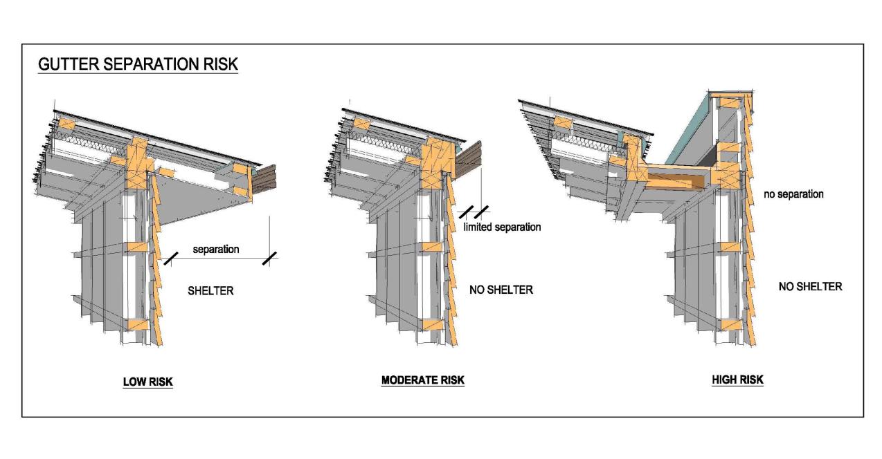
1.5 Understanding risk
Risk is comprised of the likelihood of an event happening and the consequence if it does.
Act
Good design needs to consider and address both aspects of risk.
Information
Official
the
A design that employs a sloped roof and substantial roof overhang to shed water beyond
the external walls has a lower likelihood and consequence of leakage. For example, if the
gutters were to overflow, water would fall harmlessly to the ground.
A roof with no eaves provides no shelter to the wall and the critical roof edge is adjacent to
the wall. Both the likelihood and consequence of failure have increased.
under
A building designed with a parapet and an internal gutter has a much higher likelihood and
consequence of leakage. The internal gutter and roof edge is directly over the internal
space. The wall is now reliant on the parapet flashings for protection and the lack of shelter
to the external wall remains. If the gutter were to overflow, large volumes of water would
cascade into the building.
Risk-prone features are best avoided. If this is not possible, they should be limited in use
and carefully managed through the design and building process.
Released
Page 6 of 35
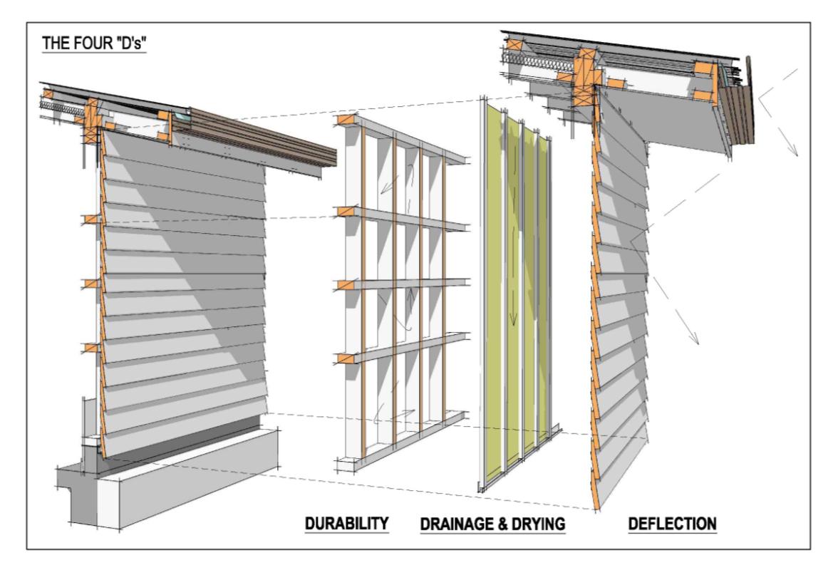 1.6 The 4Ds concept
Weather-tightness is best explained by the 4Ds concept of deflection, drainage, drying and
durability.
Deflection
Rainwater is deflected by external surfaces and the use of features such as eaves or
flashings.
Drainage
(1982)
Water that penetrates cladding is allowed to drain back to the outside; a wall cavity is a
good example.
Drying
Act
Water that does not drain back to the outside is allowed to dry out; principally through
ventilation.
Durability
Ensuring that building materials have sufficient durability to allow drainage and drying to
occur before undue deterioration occurs.
Information
Official
the
under
The first three Ds relate to moisture management. It is inevitable that any building envelope
system will be penetrated by some external moisture during its lifetime. Such moisture must
be able to dissipate quickly through drainage and drying before damage occurs. Keeping
building elements dry is the key goal.
Released
The fourth D – Durability, relates to the intended life of the building element. If any element
of the building system suffers premature failure – usually from moisture-induced
deterioration – then the system has failed.
Page 7 of 35
1.7 Design requirements
Section 17 of the Building Act 2004 requires all building work to comply with the Building
Code. As noted above, these weather-tightness requirements assume that the design of
school buildings meets Building Code standards.
There are a number of pathways designers can follow to meet the Building Code.
Approved solutions
These include Acceptable Solutions and Verification Methods (testing or calculation
methods) published by the DBH. Often these cite New Zealand or joint Australian / New
(1982)
Zealand Standards.
The Approved Documents can be downloaded free from:
www.dbh.govt.nz/building-code-
compliance-documents-downloads
Act
The combined use of Approved Solutions with this document are deemed a “complying
design” in terms of this document.
Alternative solutions
Design solutions not covered by Acceptable Solutions or Verification Methods are known as
"alternative solutions". These can include cladding systems from manufacturers or one-off
designs created by the designer(s).
The design must still comply with the requirements of this document
and must be peer
reviewed.
Information
The peer review process can be in-house for larger design practices where the project
manager is satisfied the peer review was undertaken by another person, suitably
experienced and qualified, but with no direct involvement in the design of the building.
Non-complying design
Official
Where a design does not comply with this document the design must be
submitted to the Ministry's National Property Advisor for a technical
determination on whether the design is acceptable, or what changes, if
the
any, are required.
under
Released
Page 8 of 35
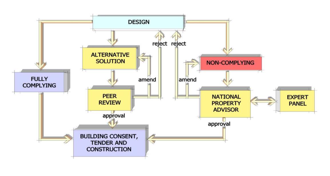 Design pathways
(1982)
Act
Building Code
Weather-tightness is governed by two clauses within the Building Code; B2 - Durability and
E2 - External Moisture.
Sub-clause B2.2 requires buildings to be sufficiently robust that they can be maintained
Information
without the need for significant reconstruction. Sub-clause E2.2 requires adequate
resistance to the penetration and accumulation of external moisture.
The relevant Approved Documents, such as E2/AS1, that are deemed by the DBH to satisfy
the Building Code. Those „not limited in scope‟ apply to all buildings, whereas those „limited
in scope‟ apply to a certain buildings as defined by the scope within that document.
Official
Acceptable Solution B2/AS1 (not limited in scope)
Acceptable Solution B2/AS1 specifies the durability requirements of building elements
based on the difficulty to detect or access problems e.g. it specifies minimum levels of
the
timber treatment for timber used in different parts of buildings subject to varying at risk of
decay.
Verification Method B2/VM1 (not limited in scope)
Verification Method B2/VM1 provides evaluation methods for durability by taking into
under
account the in-service history, laboratory testing and proven performance of similar
materials.
Acceptable Solution E2/AS1 (limited in scope)
E2/AS1
is limited to buildings less than three stories or less than 10 metres in height and
provides a means for achieving weather-tightness of the building envelope using common
materials, products and processes.
Acceptable Solution E2/AS1 is a primary reference and must be read in conjunction
Released
with this document.
Please note E2/AS1 and E2/VM1 are currently under review with new editions due to be
published during 2011.
Page 9 of 35


There are design limitations on height within E2/AS1 and certain common materials, such
as concrete masonry, are not included. However, E2/AS1 includes a wide range of wall and
roof cladding systems commonly found in school buildings which include:
Wall claddings
Roof claddings
Brick veneer
Butyl/EPDM membranes
Stucco
Concrete/clay tiles
Timber weatherboards
Pressed metal tiles
(1982)
Fibre cement weatherboards
Profiled metal
Profiled metal
Fibre cement sheet
Act
Plywood sheet
EIFS (Proprietary plaster on
polystyrene)
Verification Method E2/VM1 (limited in scope)
This provides a means for testing and approving the weather-tightness of various wall
cladding systems other than those included in E2/AS1. Information
1.8 Other references
Other reference documents relevant to weather-tightness design and the procurement and
use of appropriate building systems and materials include:
Ministry of Education Property Handbook -
www.minedu.govt.nz/PropertyHandbook
NZS 3604:1999
New Zealand Metal Roofing Manufacturers' (NZMRM) Code of Practice for Metal
Official
Roofing and Wall Cladding, Version 2 -
www.metalroofing.org.nz
Code of Practice for Torch-on Membrane Systems Roof and Decks -
www.membrane.org.nz the
DBH - External Moisture - An Introduction to Weather-tightness Design
Principles -
www.dbh.govt.nz
under
Released
Page 10 of 35
 Section 2: Timber framing and plywood
2.1 Treatment
Section 2: Timber framing and plywood
2.1 Treatment
To conform to Building Code Clause B2 Durability requirements, most timber and certain
wood-based products are treated with a specific type and concentration of treatment to
resist various biological hazards (insects and fungal decay) associated with typical end
usage. Timber treatment can be seen as a relatively inexpensive insurance against
premature and destructive decay should the timber be exposed to elevated moisture levels. (1982)
2.2 Hazard Class
Typical end-use situations are ranked according to their level of risk into one of six Hazard
Classes, each identified by the letter H and a number ranging from H1 – H6. There are
Act
subclasses such as H3.1 and H3.2. Timber selected for use in any situation must contain
the appropriate level of treatment for the Hazard Class associated with its end use.
The relevant Standards are NZS 3602, NZS 3640 and AS/NZS1604.3. There is also a DBH
guide on the use of treated timber.
Please note the treatment of timber used in buildings is
currently under review.
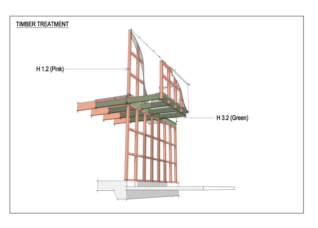
2.3 Timber framing
All timber floor, wall and roof framing to be used in school buildings shall
have a minimum treatment level of H1.2, except for cantilever joists to
Information
enclosed decks, which shall have a minimum treatment level of H3.2.
Official
the
under
Released
Cantilevered decks are seldom found in school buildings.
Page 11 of 35
2.4 Plywood
Non-complying levels of light organic solvent preservative (LOSP) based treatments in
plywood have been a contributing factor to a number of cladding failures in schools.
All plywood used for cladding, roof substrates, rigid air-barriers and sheet
bracing on the outside of external wall framing shall be H3.2 copper
chrome arsenic (CCA) treated and fixed with stainless steel fixings. Until
further information is available H3.1 LOSP is not a permitted treatment for
plywood in school buildings.
(1982)
Act
Information
Official
the
under
Released
Page 12 of 35
 Section 3: Roofs
Roofs need to be designed and constructed to minimise potential leakage. Simple,
uninterrupted roof shapes with a healthy slope and ample overhang are proven to work
well. Complex roof shapes, low-pitch roofs, and roofs with numerous junctions and
penetrations are at far greater risk of leakage.
3.1 Metal roofing
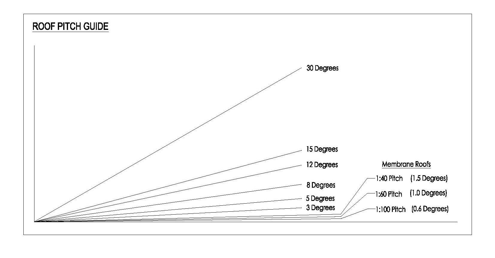
3.1.1 Roof pitch
(1982)
Lack of pitch is a primary cause of roof leakage at flashing junctions and roof penetrations.
Increasing roof pitch reduces the risk of leakage and prolongs roof life.
Act
For new buildings the minimum roof pitch for trough section and
trapezoidal section roofs shall be 5º and for corrugated roofs, 12º.
Information
Official
the
For replacement of existing roofs the minimum pitch shall be 3˚ for trough
section and trapezoidal section roofs and 8˚ for corrugated steel roofs,
except where these pitches cannot be achieved without disproportionate
cost and where there has been satisfactory performance of the roof at the
under
lower pitch.
Curved metal roofs are not recommended. Curved roof designs may be considered where
there is specific guidance for installing the product in a manufacturer‟s literature for such
design. Guidance is available in the NZMRM Code of Practice.
3.1.2 Minimum roof thickness
Released
The minimum base metal thickness for all steel roofs shall be 0.55 mm.
Page 13 of 35

 3.1.3 Roof underlays
Roof underlays are breathable membranes designed to protect the roof space and structure
from the effects of moisture penetration and internal condensation. Underlay placed
directly beneath the roofing material is designed to collect and contain any condensation
that might form on the underside of the roofing material for later release as vapour when
external temperatures rise, and to provide a secure drainage pathway for any water that
might penetrate the roof cladding.
Underlays differ from vapour barriers in that underlays are designed to allow vapour to pass
through.
Underlays are typically of two types:
(1982)
Bituminous or fire retardant cellulose-based
Breathable synthetic polymer
Act
Roof underlays shall only be absorbent breathable synthetic polymer
roofing underlays with a current BRANZ Appraisal. They shall only be laid
horizontally and shall be fully supported.
Cellulose-based underlays are not permitted.
Vapour barriers such as aluminium foils and non-breathable polyethylene
plastics are not permitted.
3.1.4 Thermal break
Information
[Still awaiting technical information – addendum will be added.].
3.2 Membrane roofing
Membrane roofing made of rubber, plastic, or bitumen compounds is designed for use on
near-flat roofs. It is widely used in commercial applications, but has lately become popular
Official
in residential and school construction as a means of waterproofing low-pitch roofs and
enclosed decks.
Membrane roofing has had a typical service life of 20 years, as opposed to metal roofing
the
with 40-years plus. Because membrane roofs are typically low-pitch, they are more reliant
on workmanship. Accordingly they present a greater degree of risk and undergo a higher
incidence of failure than pitched roofs clad with conventional tile and rigid sheet roofing
materials. Accordingly, membrane roofs should be avoided where possible.
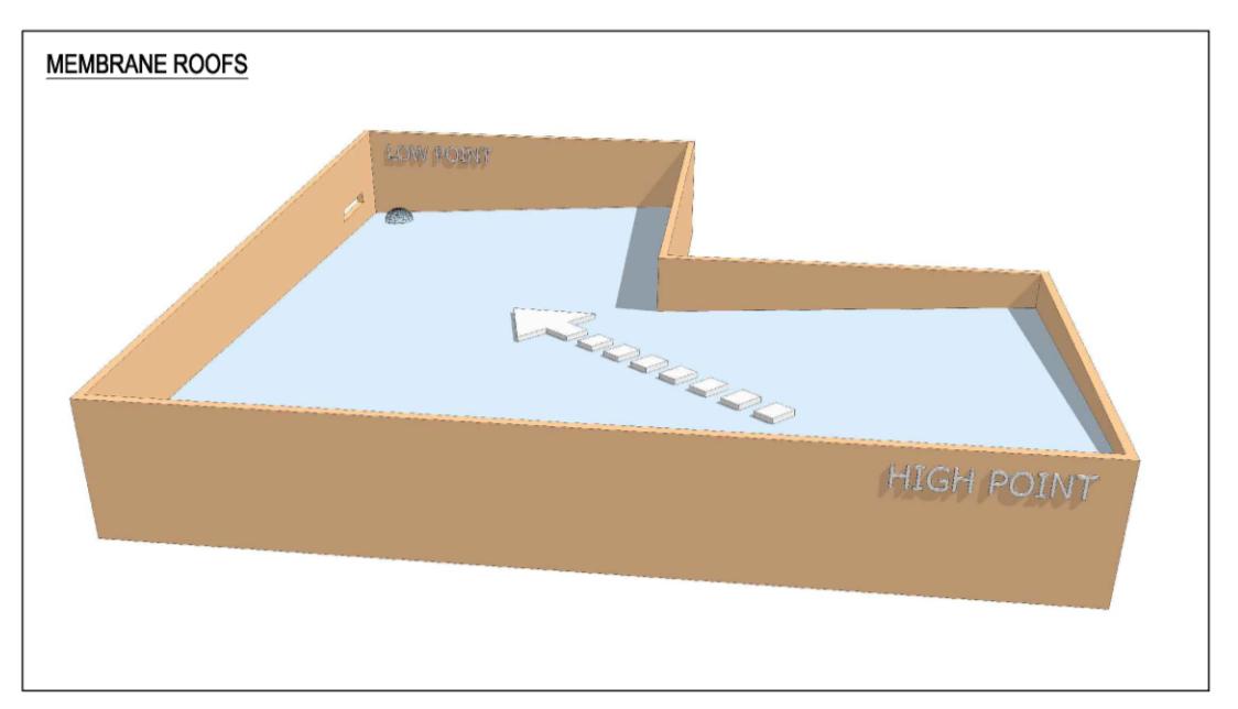
3.2.1 Membrane roof design
under
The minimum roof pitch as per E2 / AS1 is 1.5 degrees or 1:40. To assist
construction at the nominated pitch the levels of the high and low points
of the roof shall be provided on the drawings. The roof shall be designed
to minimise the number of joints and junctions in the roof membrane.
Internal gutters formed within a membrane roof add no real benefit and tend to compromise
performance of the roof by creating extra joints and laps. The following sketch shows a
Released
simple roof design without the need for a formed gutter.
Page 14 of 35


(1982)
Act
3.2.2 Membrane roof materials
Membranes shall be made of manufactured sheet material only. Liquid
applied membranes are not permitted.
Information
Approved membranes include:
Butyl and EPDM rubber in accordance with E2/AS1
Torch-on membranes, but only two layers fully-bonded and installed in
accordance with the Code of Practice and with a material warranty for a
minimum fifteen-year period and with a current BRANZ Appraisal
Synthetic plastic sheet membranes such as thermoplastic olefins (TPOs) and
Official
PVC may be used but only with a material warranty for a minimum fifteen-year
period and with a current BRANZ Appraisal
the
All such membranes must only be laid by applicators licensed and trained by the
supplier and the applicator shall provide a five year installation warranty and a
Producer Statement to the Building Consent Authority confirming the membrane
has been installed in accordance with the manufacturer‟s recommendations.
under
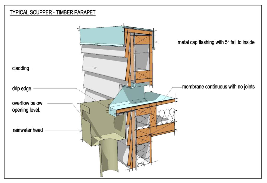
3.2.3 Outlets
Rainwater outlets for roofs shall be comprised of a proprietary clamped
metal ring and body with domed grate, or a scupper outlet in accordance
with E2/AS1 draining into an external rainwater head.
Scuppers - refer 3.6 Internal Gutters
Released
Page 15 of 35
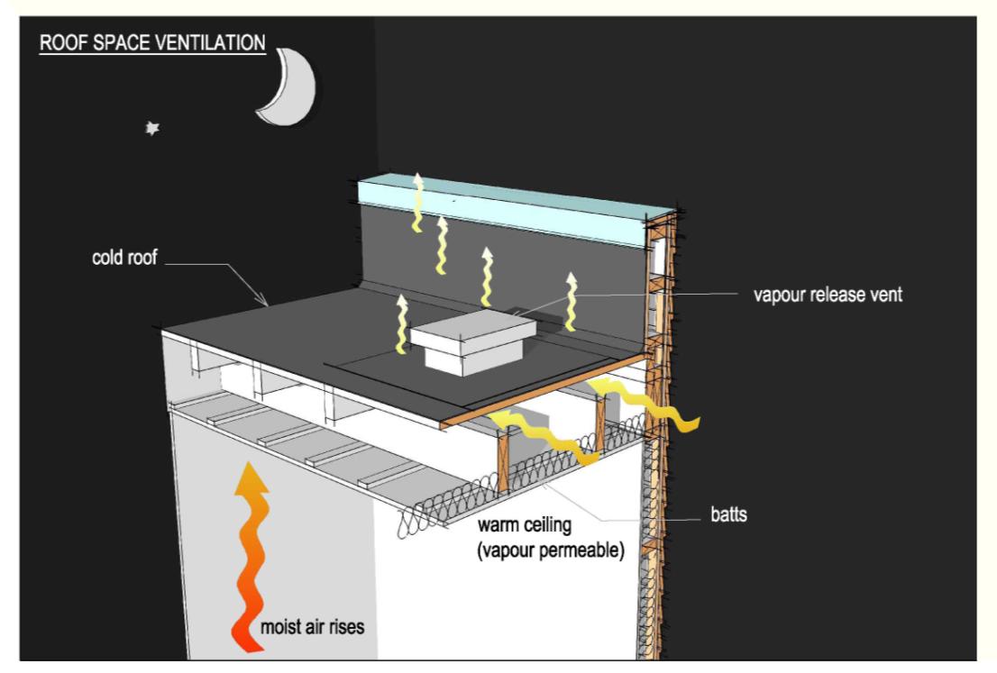 3.2.4 Roof space ventilation
Proprietary vapour vents for the roof space shall be provided at a ratio of
3.2.4 Roof space ventilation
Proprietary vapour vents for the roof space shall be provided at a ratio of
one vent (minimum vent area of 400 mm2) per 40 m2 of roof area. Cross
ventilation between the roof space voids shall be provided at, or just
below the roof substrate.
(1982)
Act
Information
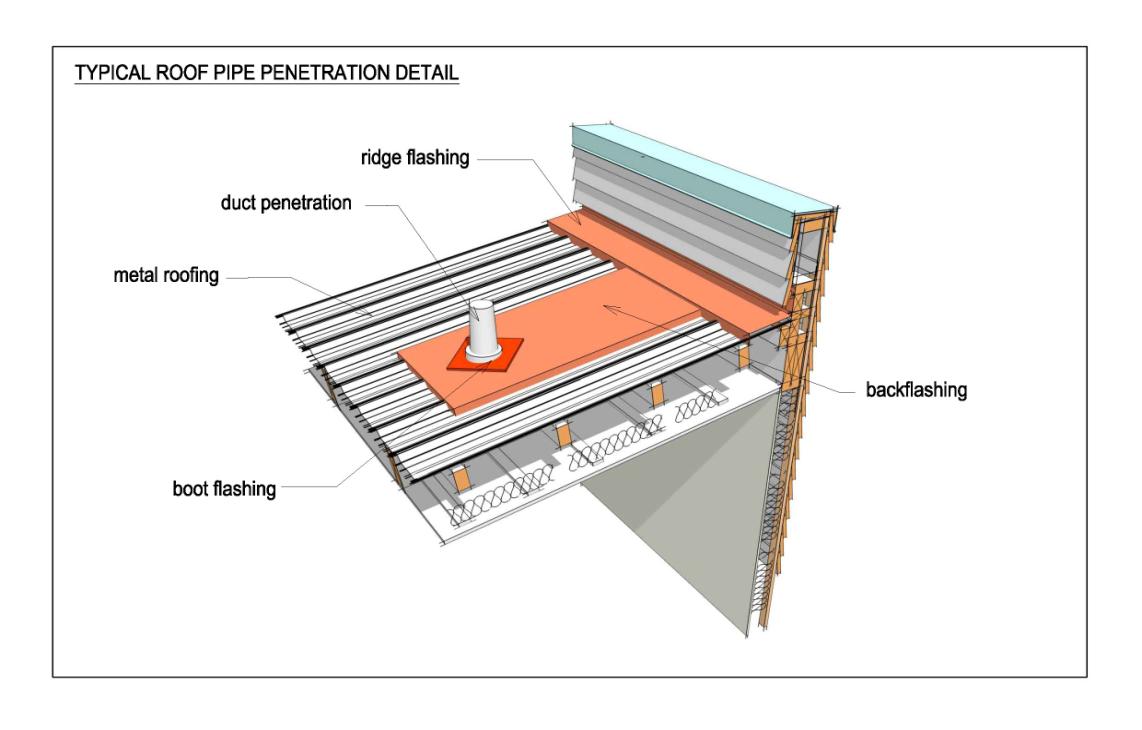
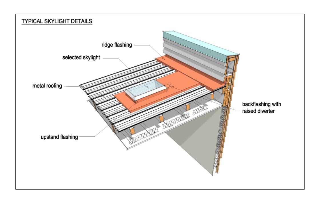
3.3 Roof penetrations (metal roofs)
Official
Roof penetrations are commonly associated with roof leaks.
It is difficult to achieve a weather-tight flashing around penetrations for vents, pipes,
the
skylights etc when they are located in an area of metal roofing. It is preferable to locate roof
penetrations close to the ridgeline, or top of the roof, to minimise the length of back flashing
needed to protect the junction between the fixture or penetration and the high point above
it.
The maximum practical length of back flashing from the penetration to the ridgeline or high
under
point is 6m.
A typical roof-pipe penetration and skylight flashing detail are:
Released
Page 16 of 35
(1982)
Act
Information
Official
the
under
Released
Page 17 of 35
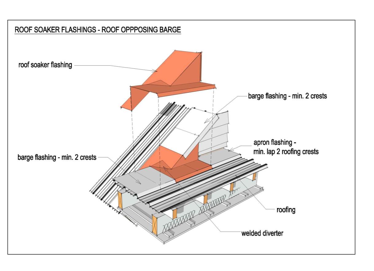
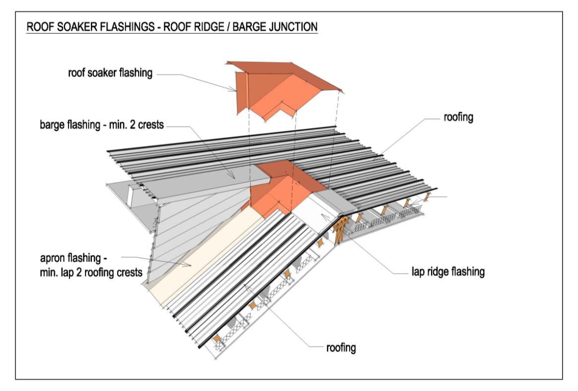 3.4 Roof junctions (metal roofs and flashings)
Poorly designed roof junctions and inadequate and poorly installed flashings are a prime
cause of leakage.
Where complex roof junctions occur, compound junction flashings are
required. These shall be constructed from welded aluminium (normally
1.6mm).
(1982)
Act
Information
Official
the
under
Released
Page 18 of 35
(1982)
Act
Information
Official
the
under
Released
Page 19 of 35
(1982)
Act
Information
All flashing joints shall be correctly lapped and shall not rely on sealant
as a sole means of weather-tightness.
Official
the
under
Released
Page 20 of 35
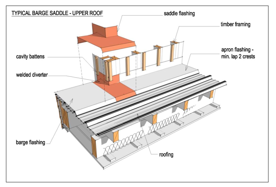
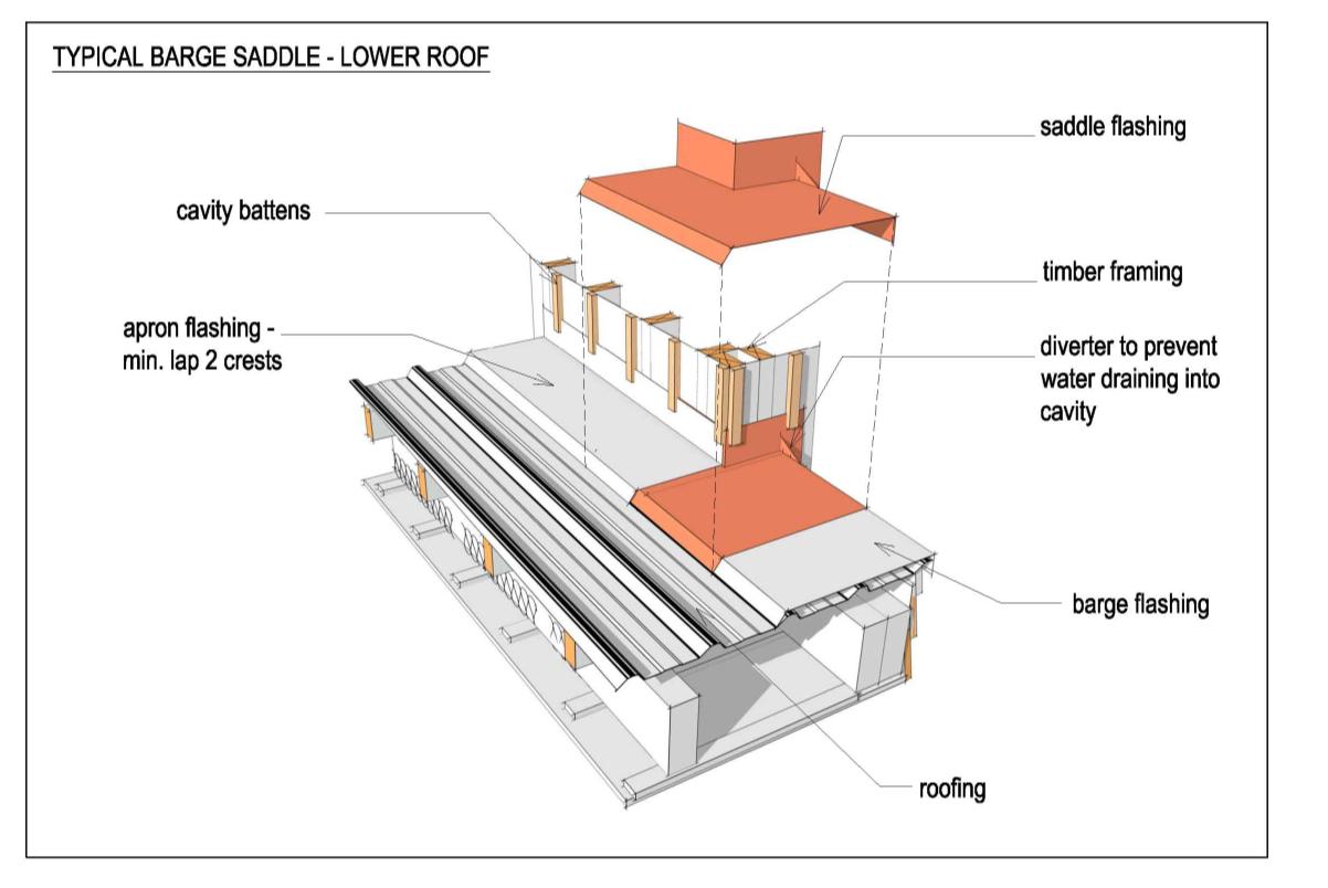
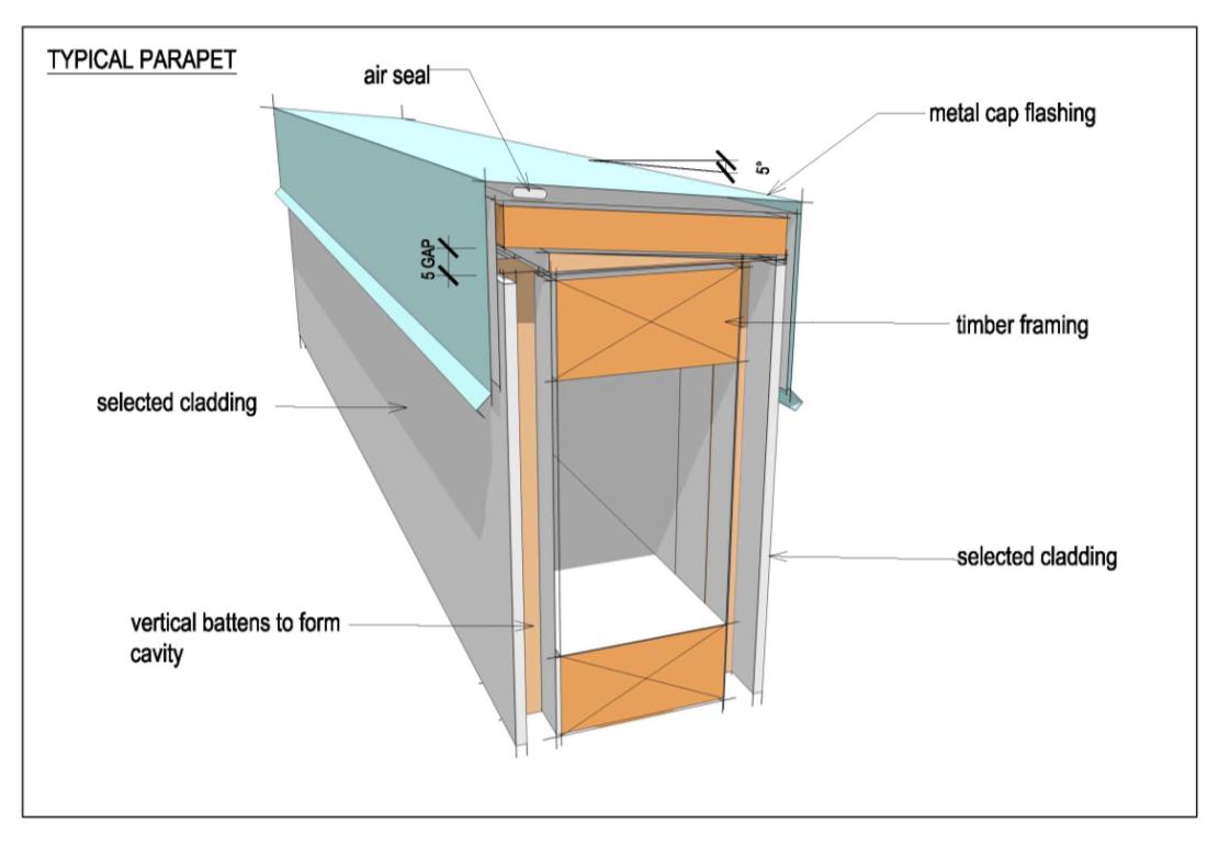
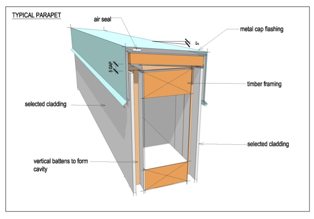 3.5 Parapets and barge flashings
A roof parapet often serves as aesthetic adornment, yet the risk associated with its use is
considerable. For a parapet to remain weather-tight it must be sloped and rely on designed
and installed junction flashings. Because roof parapets are inherently high-risk, their use
should be avoided wherever possible.
Roof parapet flashings shall be metal only with appropriate durability.
(1982)
Act
Information
Official
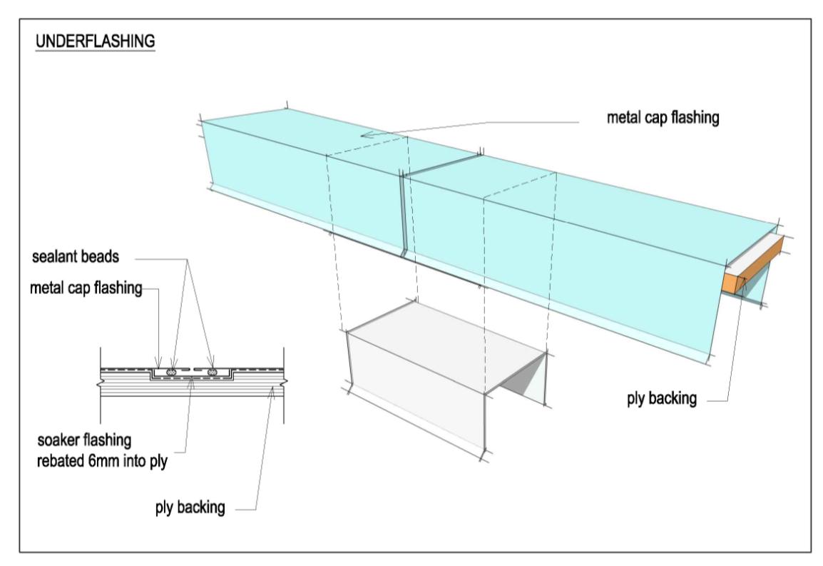
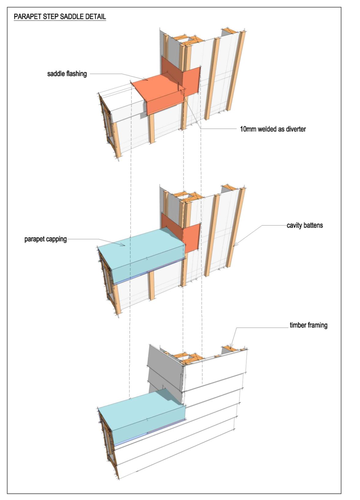
To prevent the ponding of water, level parapet tops shall be sloped to give
a minimum 5º crossfall. All joins and junctions of the cap-flashing and
saddle junctions shall be under flashed with welded aluminium flashings
(normally 1.6mm), which are rebated into the plywood substrate.
the
under
Released
Page 21 of 35

(1982)
Act
Information
Official
the
under
Released
Page 22 of 35
(1982)
Act
Information
Official
the
under
There shall be no reliance on sealant alone for weatherproofing. All
parapet flashings are to be fully supported and top fixings are not
Released
permitted. Only side fixings or concealed clips shall be used.
Lapped flashing joints and top fixings are permitted only on raking barge
flashings.
Page 23 of 35
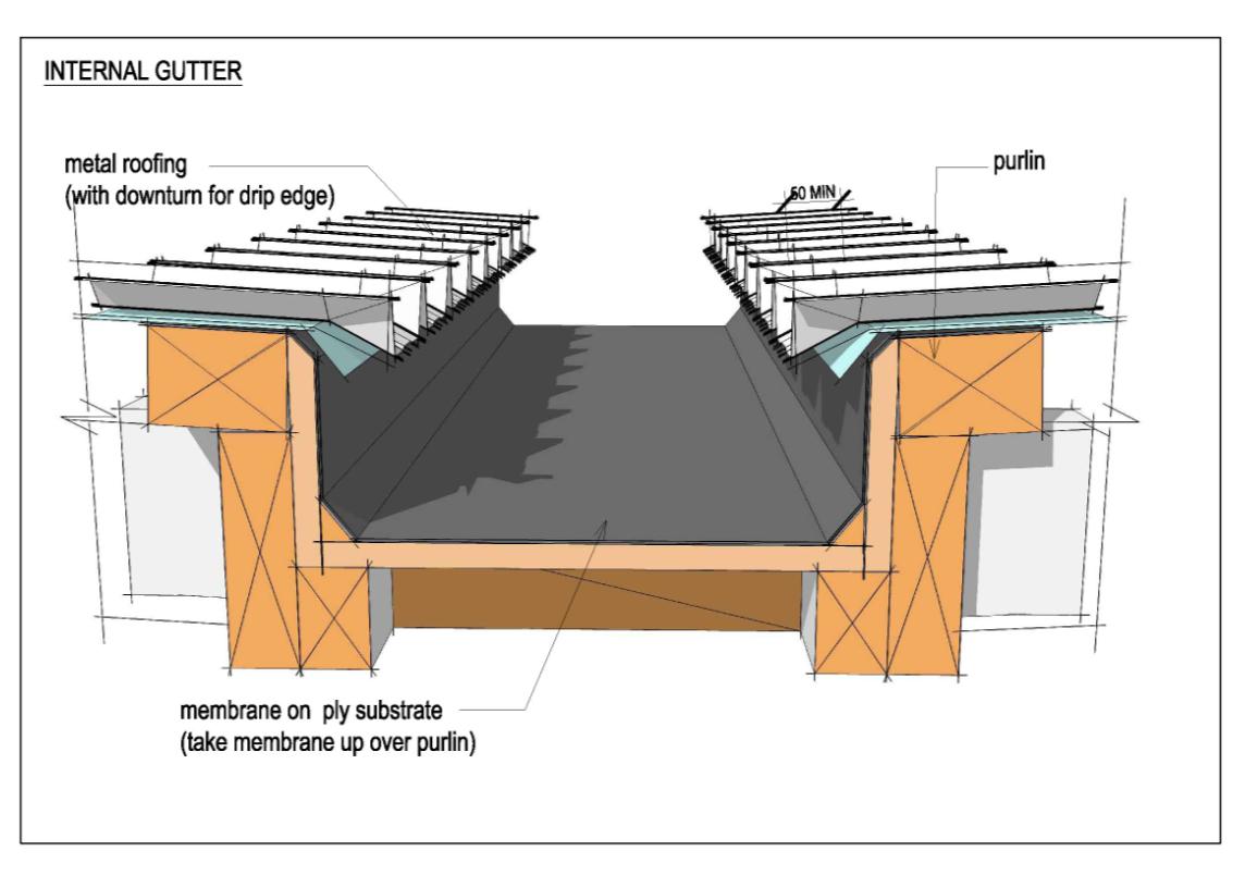 3.6 Internal gutters
Internal gutters shall have a minimum 1:100 fall with the high and low
3.6 Internal gutters
Internal gutters shall have a minimum 1:100 fall with the high and low
ends of the gutters specified on the drawings.
(1982)
Act
Information
Where gutters penetrate external walls to discharge into rainwater heads,
the full width of the gutter shall extend through the parapet into the
Official
rainwater head and terminate with an end drip-edge.
the
under
Released
Page 24 of 35
(1982)
Act
All roof gutters and downpipes shall be designed to meet the
requirements of the Building Code, Clause E1 – Surface Water.
Information
Internal gutters shall be designed for twice the “one in 50-year” rainfall
intensity.
Suitable design methods are provided in E1 / AS1 and BRANZ Bulletin 509.
Official
Where overflows are provided as a separate scupper or as an opening
within a rainwater head, the cross sectional area of the overflow shall be
1.5 times the area of the downpipe. To prevent internal flooding, overflows
the
shall be set at a height to enable them to be fully functional should the
downpipe or outlet become blocked.
Blocking the downpipe and flood-testing to check the integrity of the gutter, outlet,
downpipe, their connections and the operation of the overflow is recommended before
under
adjacent linings are installed.
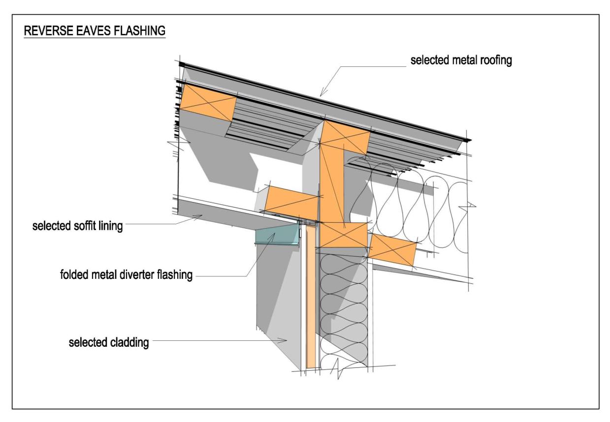
3.7 Roof eaves
Exposed undersides of roofing are 'unwashed' areas and as such are prone to premature
corrosion. Exposed rafters and beams can also inadvertently transport condensation and
rainwater to the inside.
All roof eaves must be enclosed and lined. Reverse-slope eaves must be
Released
fitted with a flashing to prevent moisture penetration.
Page 25 of 35
(1982)
Act
Information
Official
the
under
Released
Page 26 of 35
 Section 4: Wall cladding
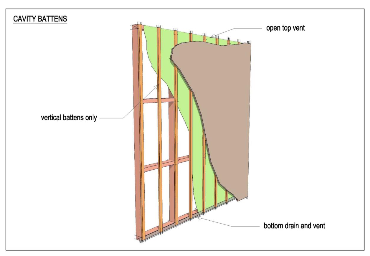
All wall claddings shall be installed over a drained and ventilated cavity.
4.1 Wall cavity
Section 4: Wall cladding
All wall claddings shall be installed over a drained and ventilated cavity.
4.1 Wall cavity
(1982)
Act
Information
Official
All cavities shall be constructed with vertical battens only. Where
horizontal support is required for cladding, flashings or wall penetrations,
the
short vertical battens shall be installed and the tops of the battens
bevelled to shed water towards the outside of the cavity.
Top ventilation of the wall cavity is required. Where the top of a cavity
coincides with a parapet, airflow from one side of the parapet cavity to the
other side of the parapet cavity shall be prevented by an airseal placed
under
beneath the parapet capping.
Released
Page 27 of 35
(1982)
Act
Wall cavities should be separated from adjacent walls and compartmentalised to avoid
undue wind pressure differentials to allow pressure equalisation or moderation to occur.
Information
Wall cavities must be separated from roof, subfloor and sub-deck areas to
allow pressure equalisation, or moderation to occur and to avoid the
transfer of undue moisture.
Battens shall be installed to enhance the openness of the wall cavity and
shall be positioned to both adequately support the cladding and provide
Official
drainage and ventilation behind junctions.
4.2 Cladding as bracing
the
No cladding shall be used as a sheet wall bracing.
When cladding is used as a wall brace, horizontal battens are required, which inhibit the
performance of the cavity.
under
4.3 Wind barrier
Generally the external cladding should be 20 times more air-permeable than the internal air
barrier. For example, with weatherboards the gaps that naturally occur at laps provide air
permeability without moisture ingress.
For low, moderate and high wind areas the internal plasterboard linings provide an
adequate air barrier, but where there are gable ends, or other areas where no internal
linings are present, then an air barrier in these locations is required. Certain building wraps
Released
are deemed to be an air barrier; refer to E2/AS1.
When the ultimate wind pressure (UWP) for any part of the wall cladding
exceeds +1,000 Pa, allowing for local pressure coefficients, then a rigid air
Page 28 of 35
 barrier such as fibre cement or plywood shall be included and designed
by the structural engineer.
A rigid air barrier may also be used for wall bracing and/or for fire rating.
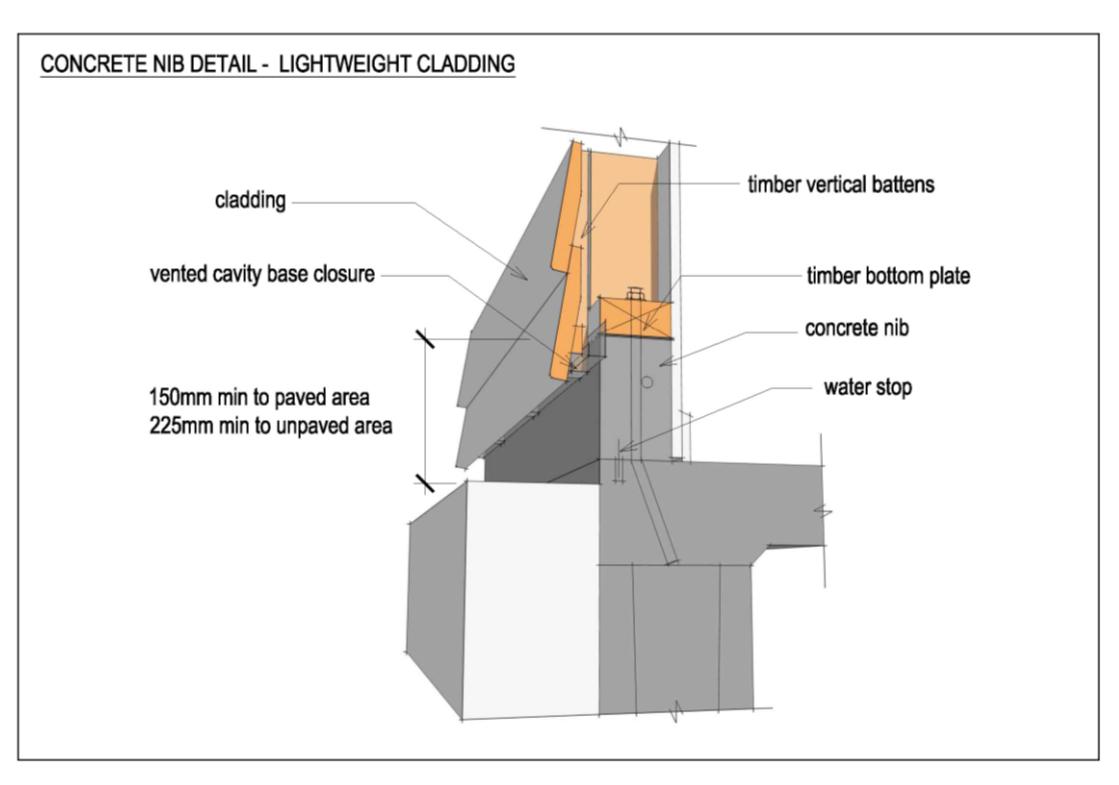
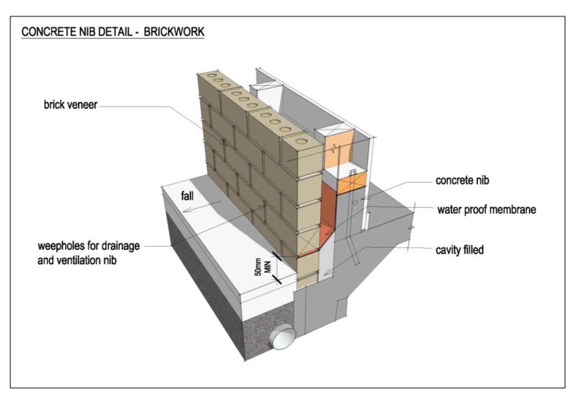
4.4 Ground clearance
All cladding to ground clearances shall meet or exceed the requirements
of E2/AS1. Where this cannot be achieved e.g. adjacent to level
thresholds, concrete nibs must be provided.
(1982)
Act
Information
Official
the
under
Released
Page 29 of 35
(1982)
Act
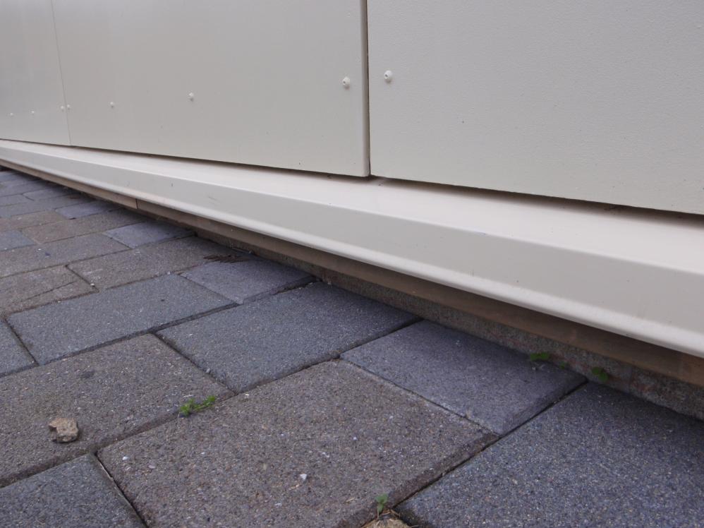
Strip drains can be used for level thresholds, but are not considered suitable for use at the
base of external walls given they can raise the humidity at the base of wall cavities.
Information
Official
the
under
Released
Page 30 of 35
 4.5 Impact damage
Cladding damage from impact is common, especially in secondary schools. The cladding
needs to be fit for purpose, which includes resistance to impact damage. In addition, the
need to replace cladding if impact damage occurs should be considered during design.
In the case of fibre cement sheet cladding, some form of bottom edge protection is
desirable. External corner protection using metal angles may also be sensible.
(1982)
Act
Information
4.6 Junction design
Official
The term „junction‟ is used to describe the intersection between two or more different
cladding systems, including where windows and doors meet the wall cladding. There are a
number of acceptable methods shown in E2/AS1 for constructing weather-tight junctions at
the
these locations, depending on the materials and the cladding systems being used.
The three necessary components of a successful weather-tight junction are:
1.
Rainscreen – provides an external rain shield to deflect water entry to the drained
cavity under
2.
Drained cavity – allows any moisture that penetrates past the rain screen to drain
away
3.
Air seal – reduces the air pressure differential between the drained cavity and
exterior, which would otherwise drive moisture into the building through any gaps
and cracks. Without a significant pressure differential, gravity takes over and water
drains out of the cavity.
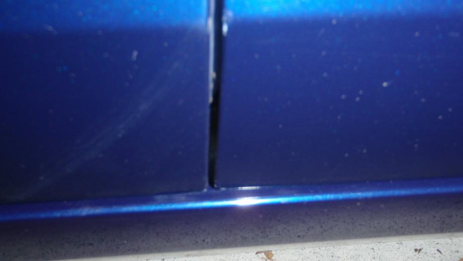
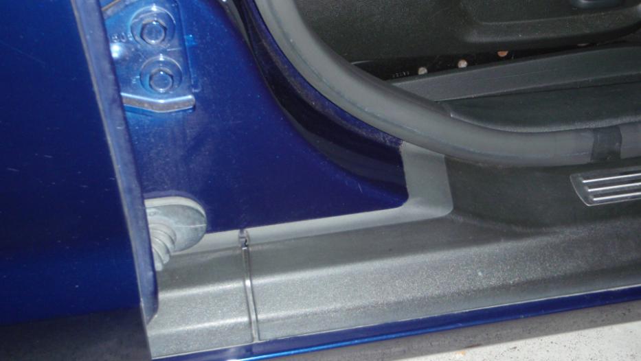
An example of a successful, everyday, weather-tight junction is a car door: The outer
surfaces of the car provides the rainscreen; there is an interior rubber air seal against which
Released
the door closes and an open drainage channel between the door and the body to allow any
water that penetrates to drain away.
Page 31 of 35
(1982)
Act
Information
Official
the
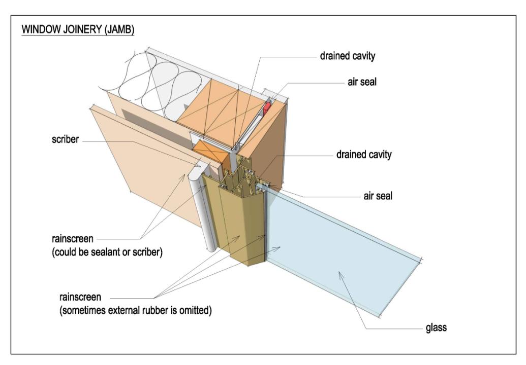
All wall cladding junctions shall be designed using the three-stage
principle of internal air seal, drained cavity and external rainscreen.
under
Released
Page 32 of 35
(1982)
Act
This illustrates the 3 stages of a successful weather-tight junction, both for the window to
cladding junction and the glass to window frame junction.
Information
Official
the
under
Released
Page 33 of 35
 Section 5: External joinery
5.1 Complex shapes
Section 5: External joinery
5.1 Complex shapes
Windows with complex shapes, raking or curved heads, or circular windows should be
avoided. Recessing of windows, other than that provided for in E2/AS1 should be avoided
as recessed sill flashings tend to accumulate rather than shield and drip water away from
opening between the window frame and the sill flashing.
Section 6: Balconies
(1982)
6.1 Balconies over internal spaces
Balconies, especially over internal spaces should be avoided, as they are inherently high
Act
risk. If they cannot be avoided, the addition of a roof over the balcony to provide partial
cover should be considered.
Where a solid balustrade is used with a balcony, the tops of the
balustrade shall be flashed and constructed the same way as a roof
parapet.
Section 7: Ground
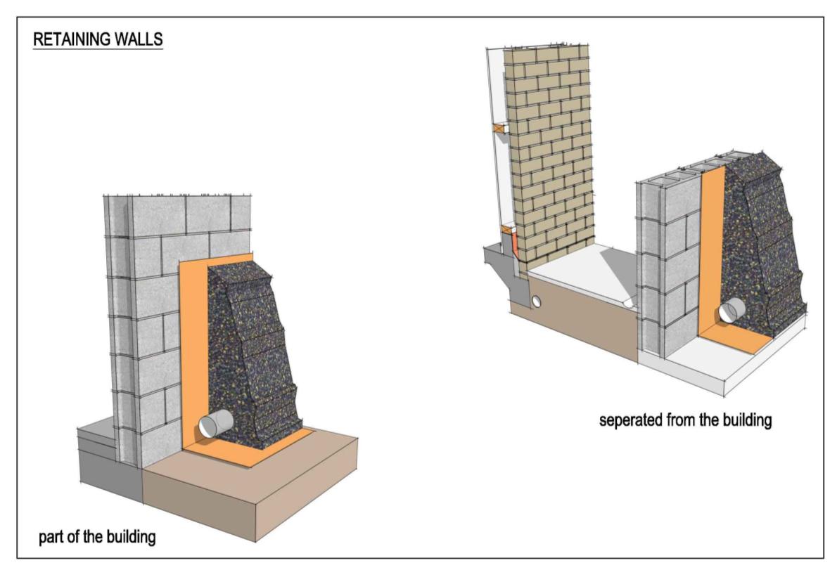
7.1 Retaining Walls
Information
Where the level of adjacent ground is above the internal floor level, an external retaining
wall, separated from the building by a minimum distance of 1.5 metres, is the preferred
option.
Official
the
under
Released
Page 34 of 35
Where this cannot be provided and the external building wall provides the retaining, then
the wall shall be constructed as follows:
(i)
A perforated subsoil drain shall be provided with its invert at the highest
point a minimum of 150 mm below floor level and sloping to an outlet,
(cesspit or silt trap) with a minimum 1:200 fall.
(ii)
Maintenance access shall be provided to allow this subsoil drain to be
cleaned by water jet.
(iii) The drain and the interface between the ground and the free draining
backfill material shall be separated with suitable geotextile filter cloth;
(1982)
(iv) If top soil is placed over the free draining backfill, this must also be
separated with geotextile filter cloth.
(v)
The wall shall be waterproofed with a sheet membrane, fit for purpose,
Act
from a major supplier of tanking materials.
(vi) The top of the membrane shall be sealed to the wall with a fixed pressure
bar or properly sealed and chased-in flashing.
(vii) The membrane shall be protected from puncture with a suitable material
such as plastic drainage mat, polystyrene sheet or fibre cement.
(viii) The backfill material shall be a clean free drainage media, fit for purpose.
(ix) Surface water shall be directed away from the wall and if necessary
intercepted by a surface drain. Subsoil drains are not intended to cope with
copious amounts of surface water and tend to silt up in that instance.
Information
Liquid applied waterproofing products shall not to be used as a means of
waterproofing retaining walls that form part of the building envelope.
7.2 Subfloors
Official
Subfloors shall be provided with surface and subsoil drains to prevent
flooding and must not be excavated or set below adjacent ground unless
an impervious retaining wall is used.
the
In all subfloor areas the ground shall be overlaid with 250 micron black
polyethylene dampcourse with all joints lapped and taped, and fitted
snugly around piles and to outside walls.
under
Cross ventilation i.e. from opposite walls, is required. In at-risk locations, a fireproof
vent cover should be installed over the vent openings.
No subfloor ventilation is allowed from damp areas below timber slated decks. Damp
air below timber slatted decks is likely to increase subfloor moisture levels. A barrier wall to
separate the sub-deck and subfloor areas without any subfloor vents is necessary.
Where there is subfloor ventilation on all four sides of a building and there
are regularly spaced vents fully compliant with requirements of NZS3604
Released
the dampcourse may be omitted.
Generally this will only occur with small isolated buildings such as prefabs.
Page 35 of 35