
ct 1982
ion
Thorpe Road
e Official Inform
(SH1 RP664/6258–6530)
NZ Transport Agency
un
Central Waikato Network Outcome Contract
17 February 2016
Pavement Renewal Report
Released
Prepared for:
s 9(2)(a)
, Manager Taupo, Downer
Prepared by:
s 9(2)(a)
, Technical Manager – Pavements
ct 1982
BE(Hons), PhD
Date:
17 February 2016
Reviewed by:
s 9(2)(a)
Opus
ion
Date:
February 2016
Status:
Draft for NZTA review
Amendment Register
Date
Changes
Rev
e Official Inform
This document is the property of Downer NZ Limited. Any unauthorised reproduction or use
of content of forbidden
un
Released
Page 2 of 46
12.1.2 Pavement Renew al Design Report
Contents
Pavement Renewal Report
1
Executive Summary
3
Introduction
8
1.
Part 1 – Setting
9 ct 1982
1.1 Renewal Drivers
11
2.
Part 2 – Investigations
14
2.1 Site Survey
14
2.2 Test pits
15
ion
2.3 Stiffness
16
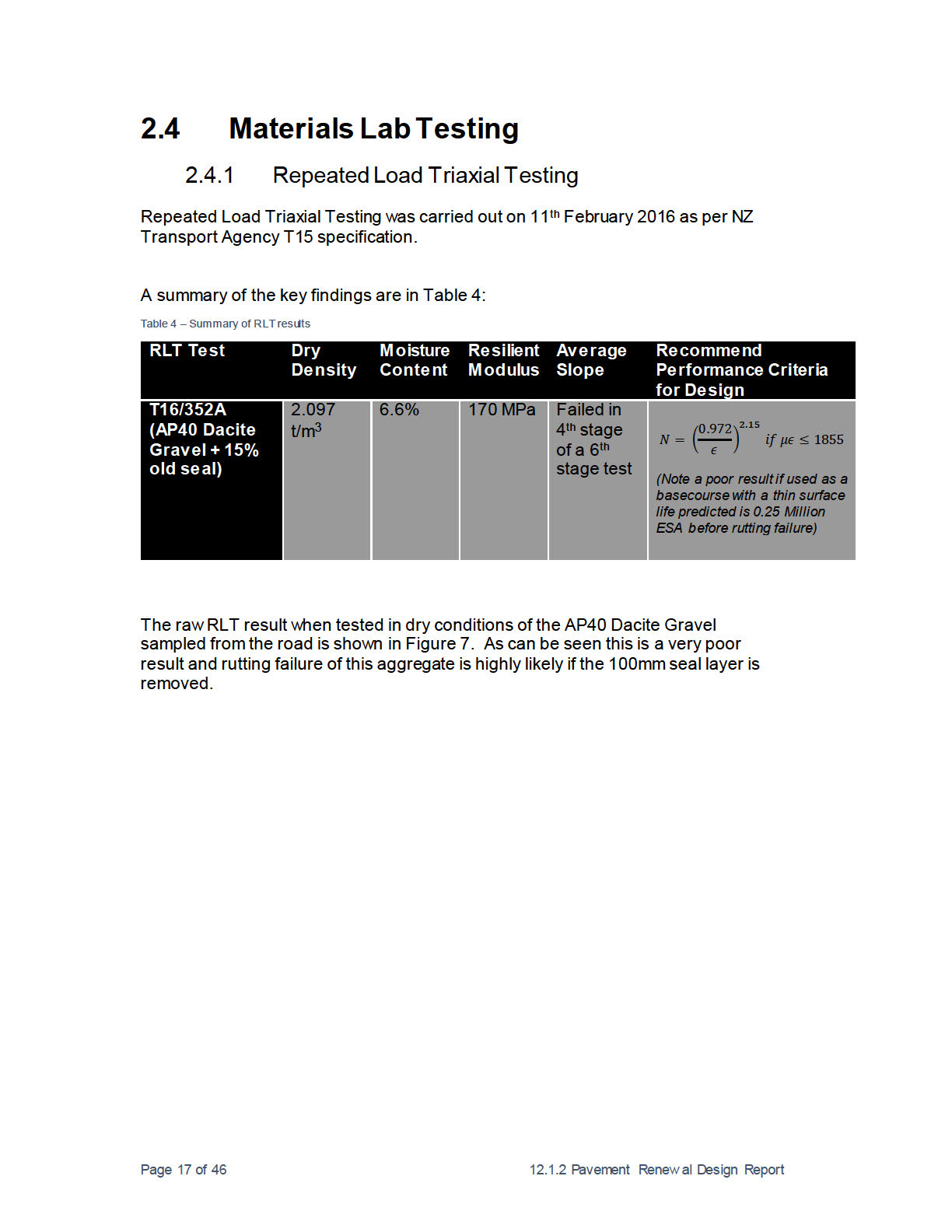
2.4 Materials Lab Testing
17
2.4.1
Repeated Load Triaxial Testing
17
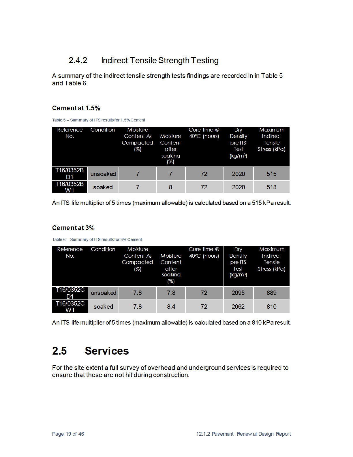
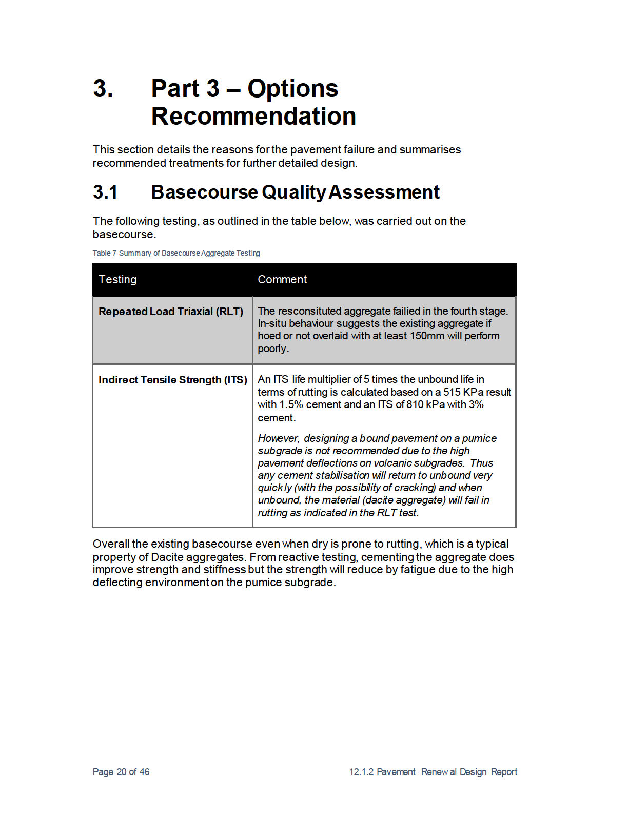
2.4.2
Indirect Tensile Strength Testing
19
2.5 Services
19
3.
Part 3 – Options Recommendation
20
3.1 Basecourse Quality Assessment
20
3.2 Failure Mode Analysis
21
3.3 Pavement Treatment Options (Treatment Selection)
22
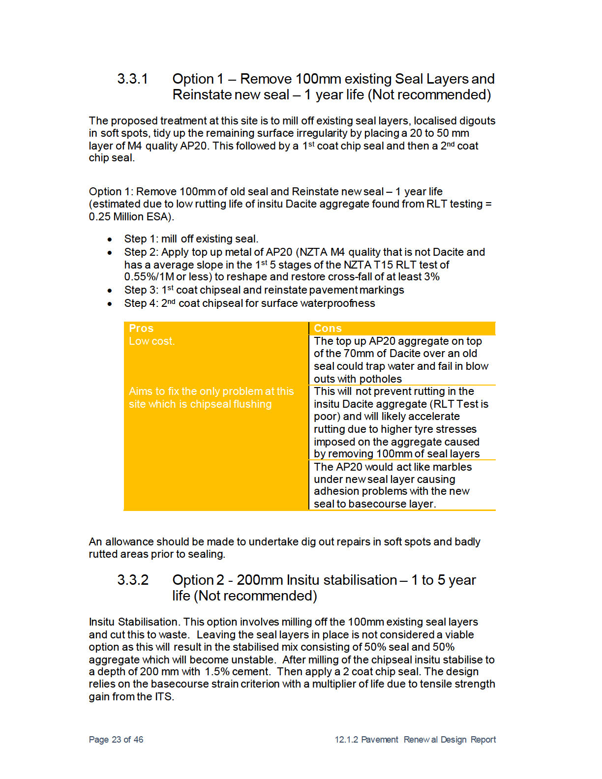
3.3.1
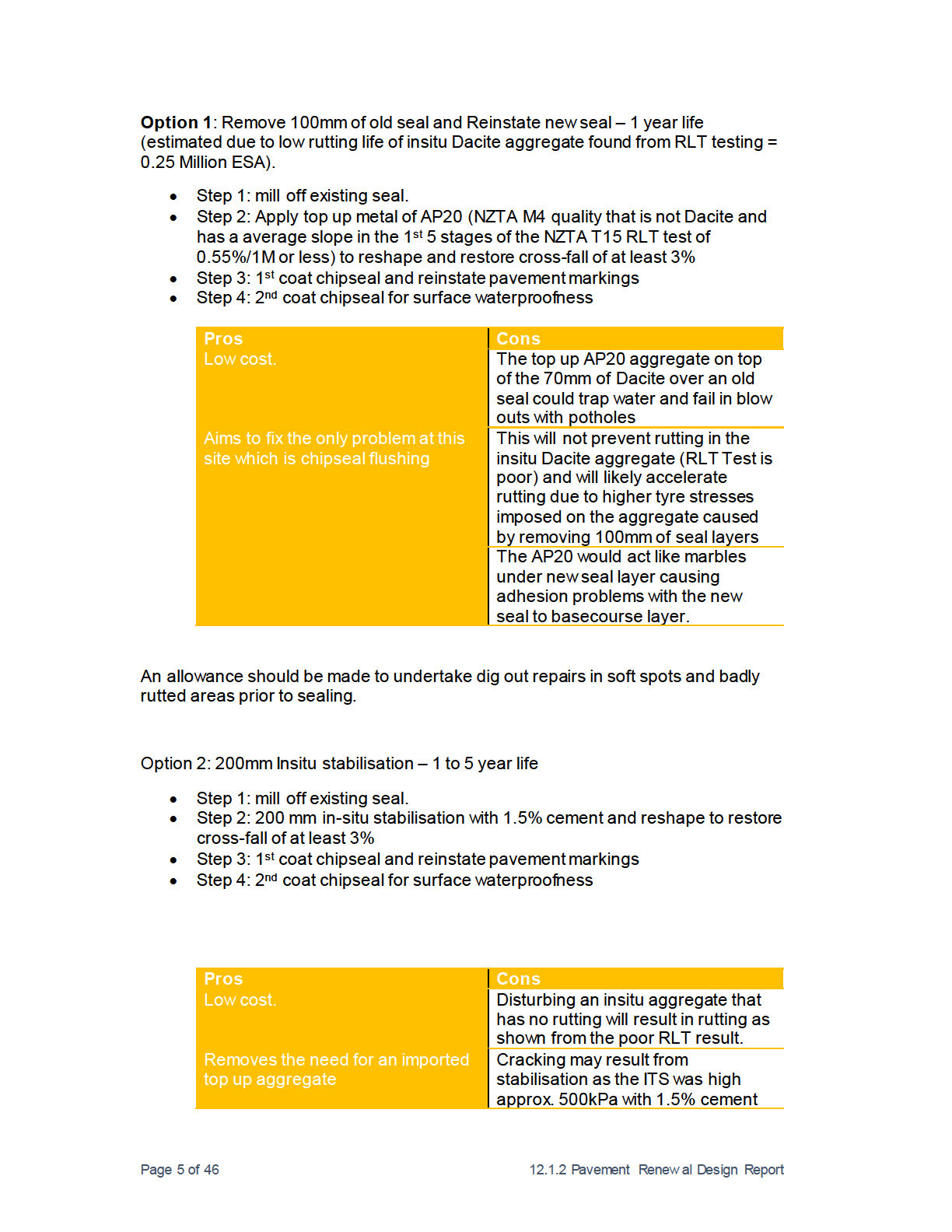
Option 1 – Remove 100mm existing Seal Layers and Reinstate
new seal – 1 year life (Not recommended)
23
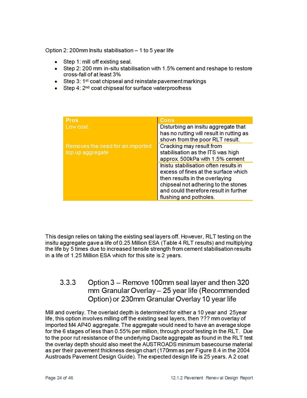
3.3.2
Option 2 - 200mm Insitu stabilisation – 1 to 5 year life (Not
recommended)
23
e Official Inform
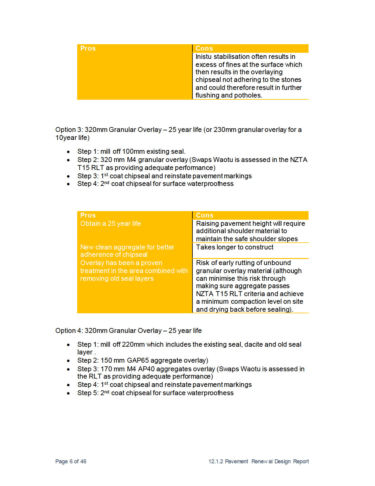
3.3.3
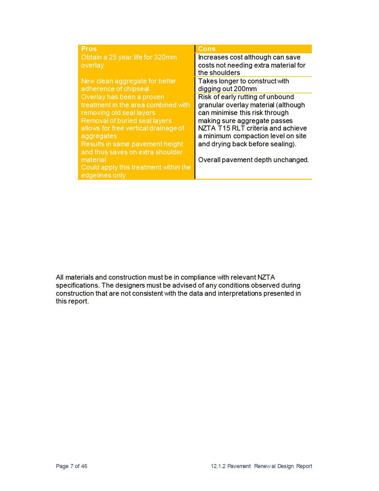
Option 3 – Remove 100mm seal layer and then 320 mm Granular
Overlay – 25 year life (Recommended Option) or
230mm Granular Overlay 10 year life
24
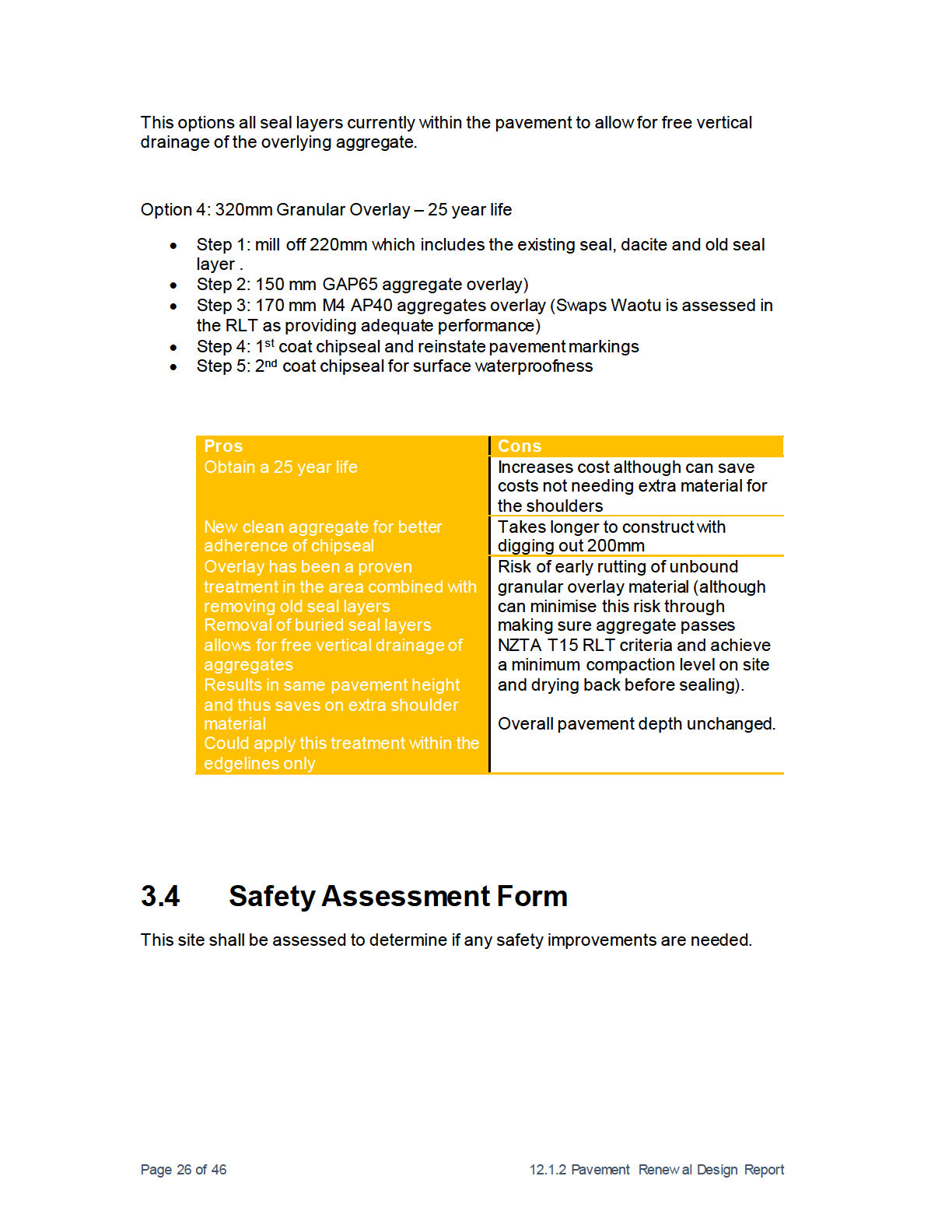
3.3.1
Option 4 – Remove 220mm (to remove surface and buried seal
layers) then overlay with 150mm GAP65 aggregate and
170mm M4 AP40 aggregates.
25
3.4 Safety Assessment Form
26
un
3.5 Options Economic Evaluation
27
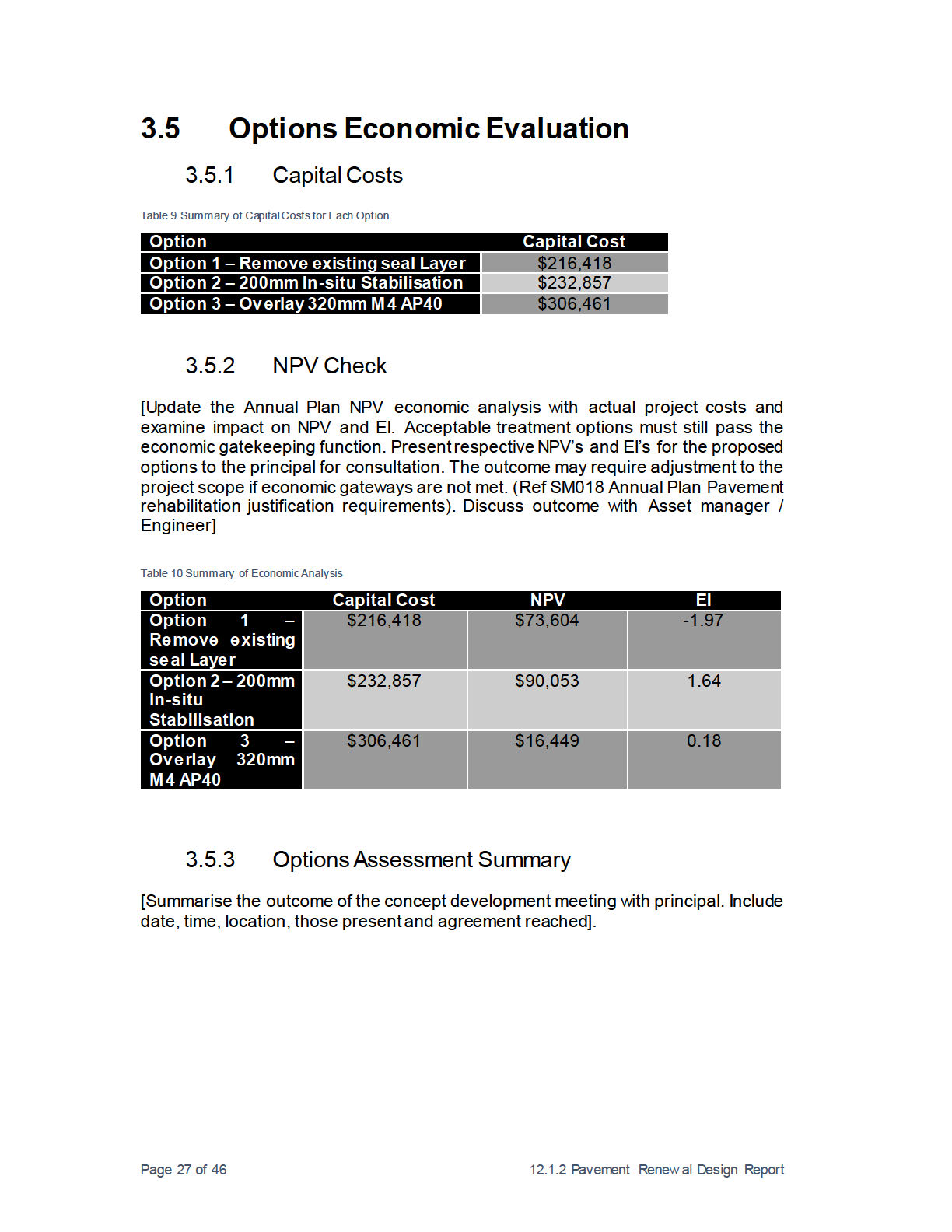
3.5.1
Capital Costs
27
3.5.2
NPV Check
27
3.5.3
Options Assessment Summary
27
4.
Part 4 – Detailed Design
28
4.1 Design Basis
28
4.2 Traffic
28
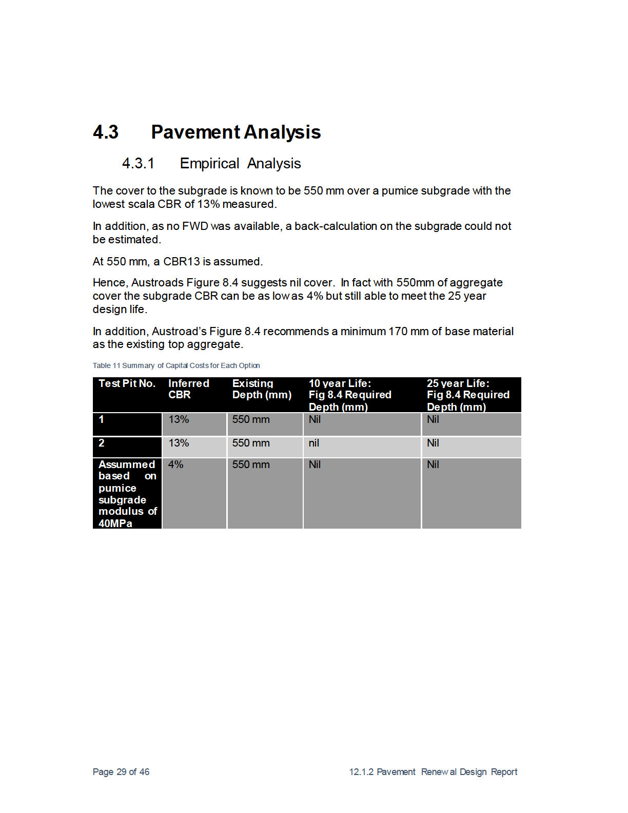
4.3 Pavement Analysis
29
Released 4.3.1 Empirical Analysis
29
Page 1 of 46
12.1.2 Pavement Renew al Design Report
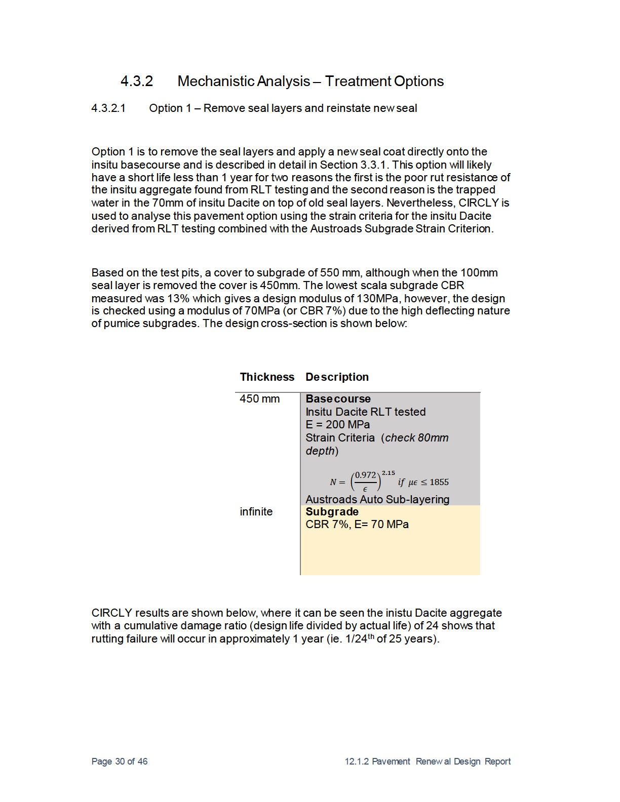
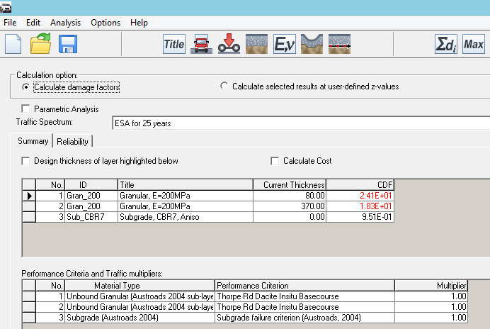
4.3.2
Mechanistic Analysis – Treatment Options
30
4.3.3
Ancillary Pavement Works.
39
4.4 Geometrics
39
4.4.1
Design Standards
39
4.4.2
Speed Environment
39
4.4.3
Typical Section
39
4.4.4
Horizontal Alignment Design
39
4.4.5
Super-elevation
40 ct 1982
4.4.6
Sight Lines
40
4.4.7
Curve Advisory
40
4.4.8
Vertical Alignment Design
40
4.4.9
Intersections
41
ion
4.4.10 Widening 41
4.4.11 Safety Improvements
41
4.4.12 Safety Audit
41
4.4.13 Additional Surfacing Requirement
41
4.5 Drainage
41
e Official Inform
un
Released
Page 2 of 46
12.1.2 Pavement Renew al Design Report
Executive Summary
This report presents the results of a site investigation and pavement renewal design
for a 300m length of pavement on SH1 near the Thorpe Road intersection south of
Atiamuri. The project is part of the Opus Central Waikato Network Outcome on
Contract on behalf of NZ Transport Agency for the 2015/2016 construction season.
The site location is defined as SH1 624 RP 6258-6530.
ct 1982
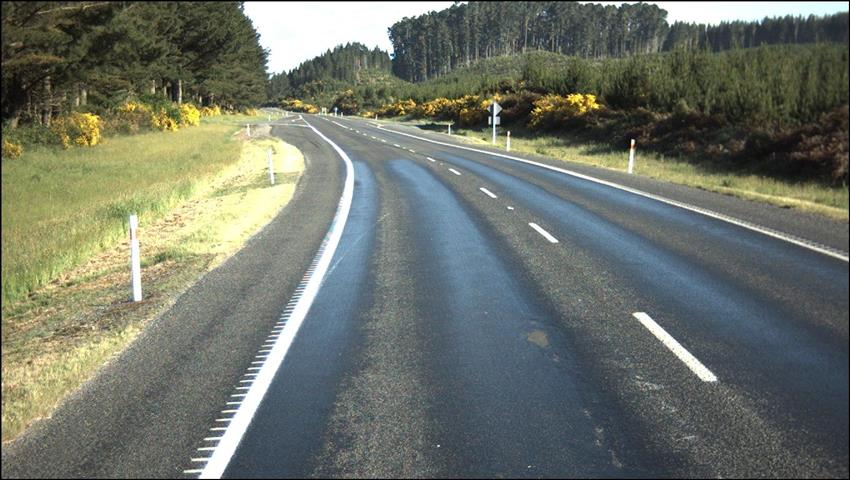
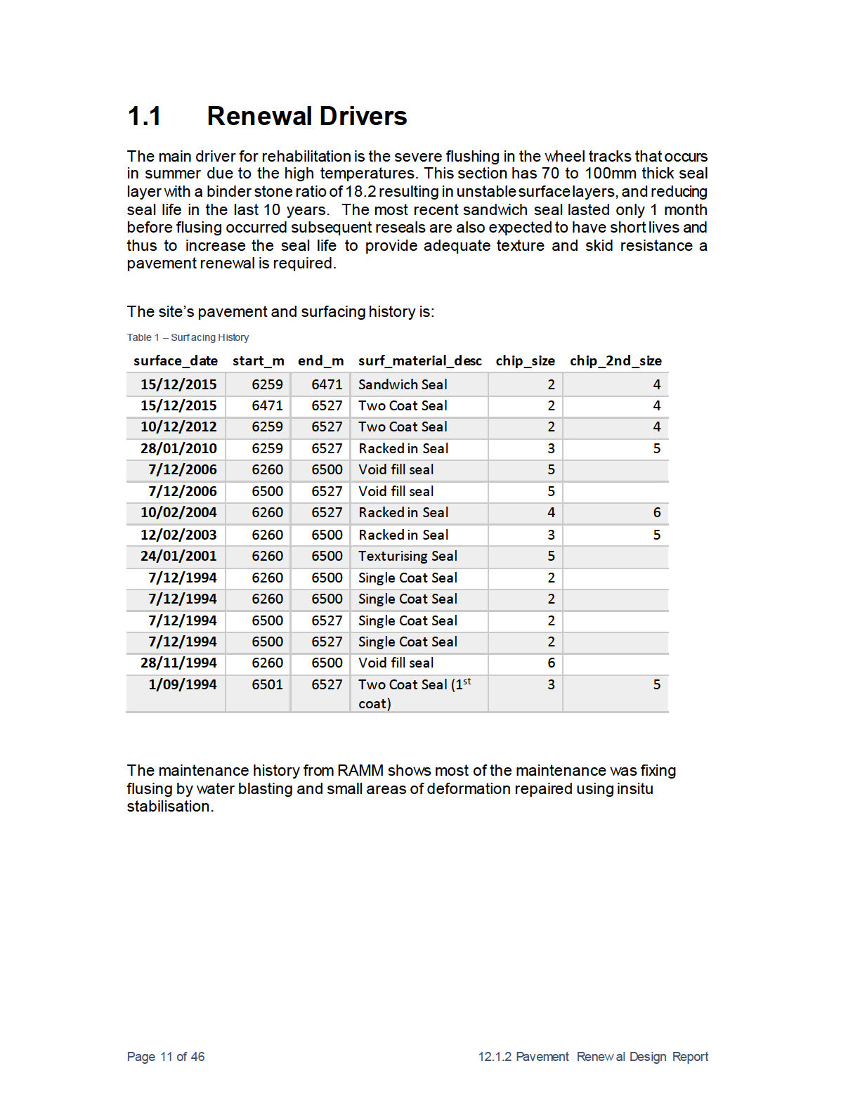
The main driver for rehabilitation is the severe flushing in the wheel tracks that occurs
in summer due to the high temperatures. This section has 70 to 100mm thick seal
layer with a binder stone ratio of 18.2 resulting in unstable surface layers, and reducing
seal life in the last 10 years. The most recent sandwich seal lasted only 1 month
before flusing occurred subsequent reseals are also expected to have short lives and
ion
thus to increase the seal life to provide adequate texture and skid resistance a
pavement renewal is required.
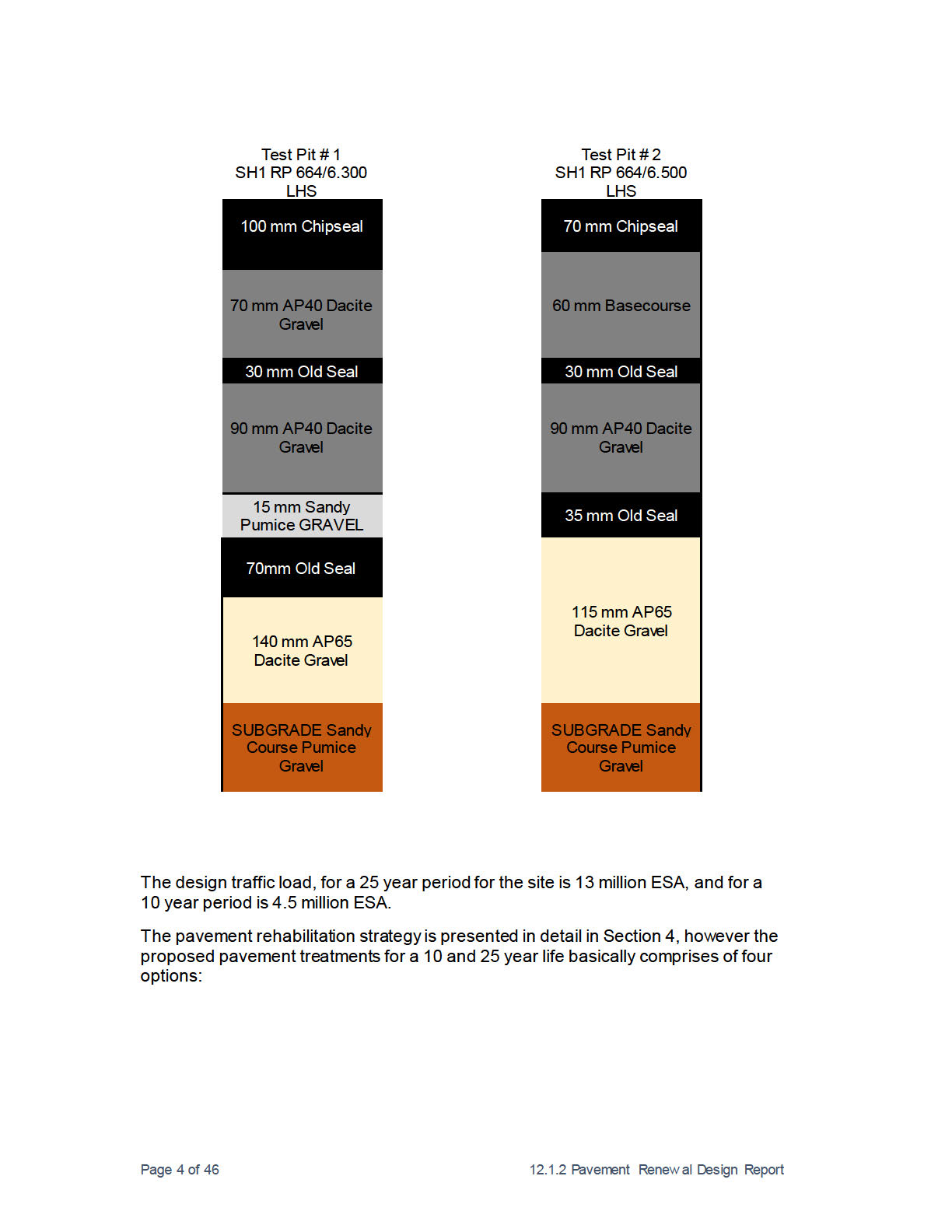
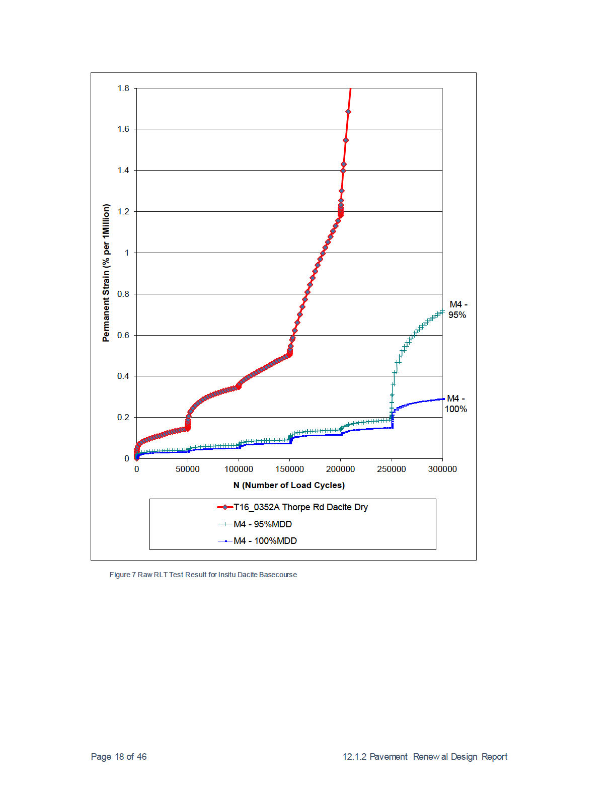
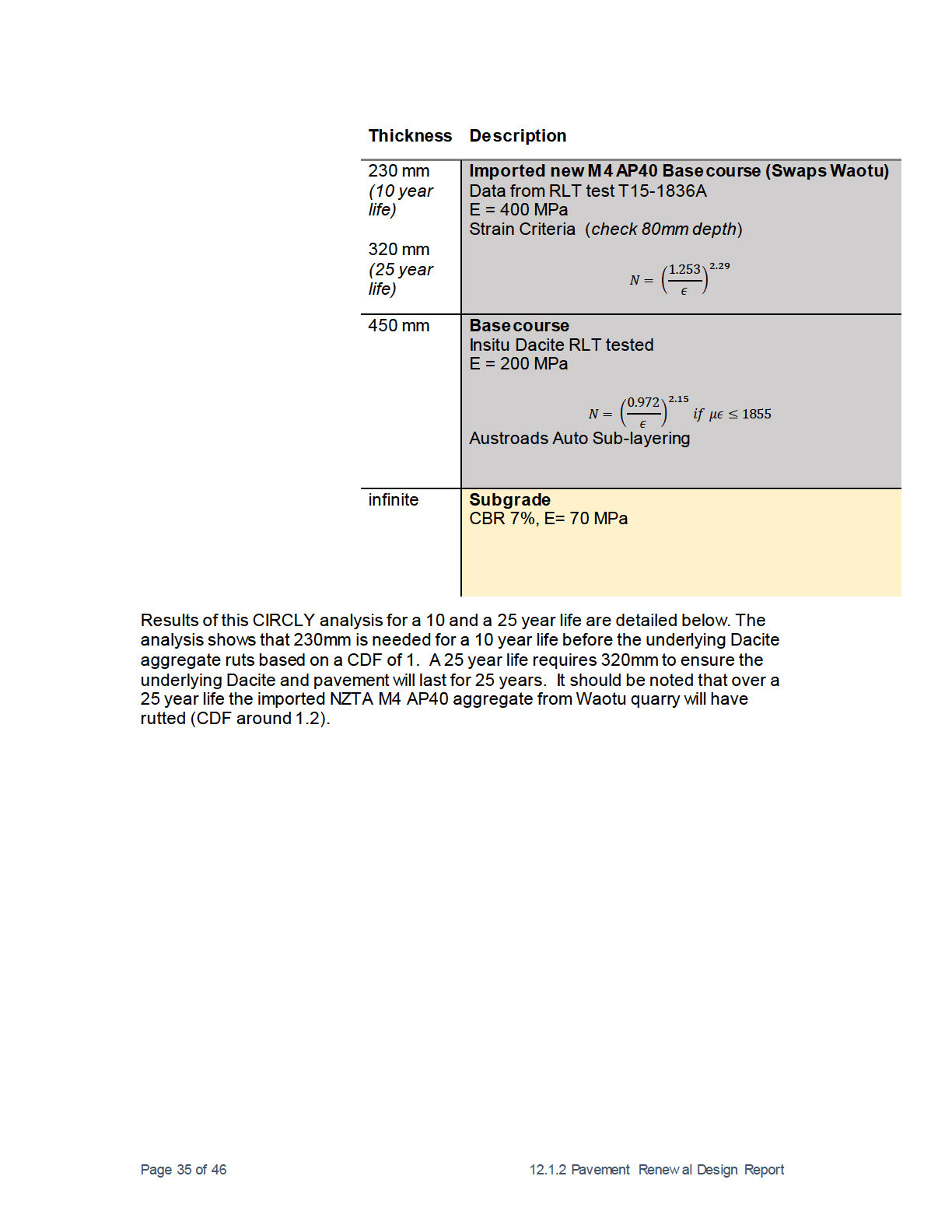
Test pits (see Figure below) show 550mm cover to a pumice subgrade where the top
100mm is existing unstable seal layers. The insitu aggregate is Dacite AP40 and the
RLT test found to have very poor rut resistance. This poor rut resistance of the insitu
Dacite aggregate at 6.6% moisture content (considered dry) governed the design
resulting in thick granular overlays to prevent the Dacite from rutting.
There is evidence of water trapped between the seal layers and a preference is
given to removing the seal layers.
e Official Inform
un
Released
Page 3 of 46
12.1.2 Pavement Renew al Design Report
ct 1982
ion
e Official Inform
un
Released
ct 1982
ion
e Official Inform
un
Released
ct 1982
ion
e Official Inform
un
Released
ct 1982
ion
e Official Inform
un
Released
Introduction
This report presents the results of a site investigation and pavement renewal design
for a 300m length of pavement on SH1 near the Thorpe Road intersection south of
Atiamuri. The project is part of the Opus Central Waikato Network Outcome on
Contract on behalf of NZ Transport Agency for the 2015/2016 construction season.
The site location is defined as SH1 624 RP 6258-6530.
ct 1982
The reports objectives are to:
• Define the motivation for pavement renewal
• Summaries of the pavement investigation information, including
o Test pits
ion
o Material testing
• Recommend suitable pavement renewal design options
e Official Inform
un
Released
Page 8 of 46
12.1.2 Pavement Renew al Design Report
 1.
Part 1 – Setting
1.
Part 1 – Setting
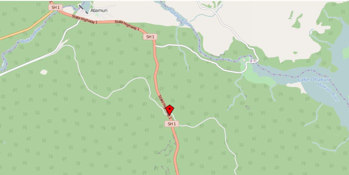
Thorpe Road site is a rural State Highway road, located in the Central Waikato
region.
A map showing the site location is presented in Figure 1.
ct 1982
ion
Figure 1: Location of site
An inspection of the site was carried out. Key observation from the site are as
follows:
• The surface comprises of multipal chipseal layers that soften in warm
weather.
e Official Inform
• Flushing is in all four wheel tracks (Figure 2).
• In some areas the flushed chipseal has stucked to tyres and strips removed
from the wheel tracks (Figure 3).
• The geometric alignment is straight (relatively horizontal) with a large radius
curve.
un
• The posted speed limit is 100 km/hr.
• This site has had multiple seals due to short lives obtained caused by
flushing. Latest sandwhich seal applied in December 2015 flushed within a
month.
• Recent multiple fatality crash site combined with short seal life due to multiple
soft seal layers prompted this pavement renewal design to ensure the
applied chipseal surface will have sufficient texture depth to maintain skid
resistance.
Released
Page 9 of 46
12.1.2 Pavement Renew al Design Report

ct 1982
ion
e Official Inform
un
Released
ct 1982
ion
e Official Inform
un
Released

ct 1982
ion
e Official Inform
un
Released
ct 1982
ion
e Official Inform
un
Released
 2.
Part 2 – Investigations
2.
Part 2 – Investigations
This section summarises the investigations completed to date.
2.1
Site Survey
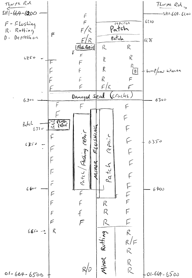
A walk-over on the site was carried out, defects were continuous wheel track
flushing and some seal loss due to the seal sticking to the tyres.
ct 1982
ion
e Official Inform
un
Released
Page 14 of 46
12.1.2 Pavement Renew al Design Report
2.2
Test pits
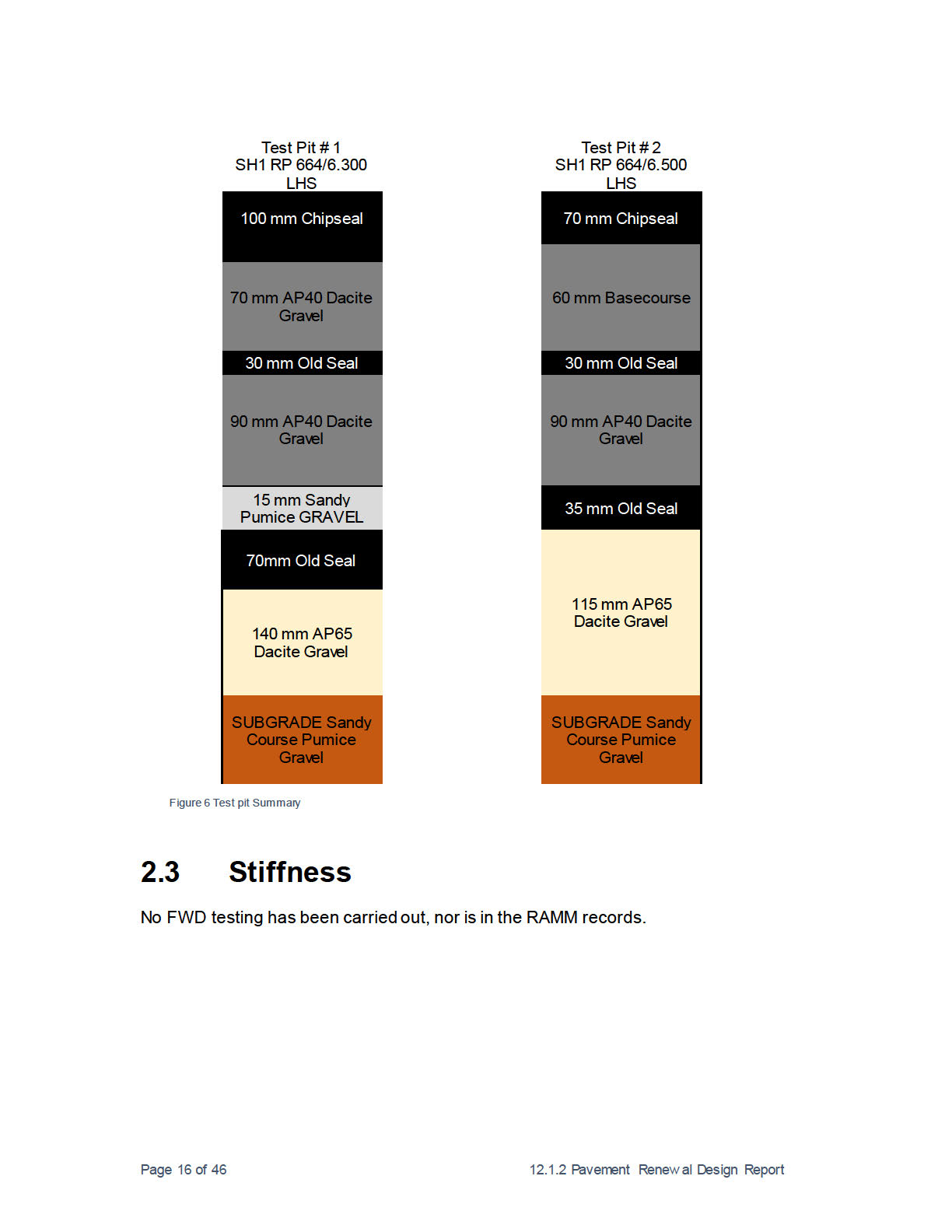
Two test pits were excavated at the site on 9th February 2016. Test pits logs and
Scala Penetrometer results are presented below, and layer thicknesses and
descriptions are summarised in Figure 6.
The tests pits in the rehabilitation section generally show:
ct 1982
• 70 to 100 mm flushed and soft chipseal surfacing layers
• 70 mm of AP40 basecourse aggregates (Dacite)
• 30 mm of old seal
ion
• 90 mm of AP40 basecourse aggregates (Dacite)
• 35 to 75 mm of old seal
• 115 mm to 140 mm AP65 subbase aggregate (Daci e)
• Subgrade (Pumice).
• Total pavement thickness (includes seal layers) of 550mm with a scala
measured subgrade CBR >13% (
note as the subgrade is pumice it is likely
the modulus based on back calculated Falling Weight Deflectometer testing
is 30 to 50 MPa)
e Official Inform
un
Released
Page 15 of 46
12.1.2 Pavement Renew al Design Report
ct 1982
ion
e Official Inform
un
Released
ct 1982
ion
e Official Inform
un
Released
ct 1982
ion
e Official Inform
un
Released
ct 1982
ion
e Official Inform
un
Released
ct 1982
ion
e Official Inform
un
Released
ct 1982
ion
e Official Inform
un
Released
ct 1982
ion
e Official Inform
un
Released
ct 1982
ion
e Official Inform
un
Released
ct 1982
ion
e Official Inform
un
Released

ct 1982
ion
e Official Inform
un
Released
ct 1982
ion
e Official Inform
un
Released
ct 1982
ion
e Official Inform
un
Released
4.
Part 4 – Detailed Design
This section describes the analysis based on the methodology related to the
accepted option from Part 3.
4.1
Design Basis
Pavement design analysis have been undertaken using the procedures and
ct 1982
performance criteria as detailed in the AUSTROADS (2012) Guide to Structural
Design of Road Pavements, the accompany TNZ (2007) Supplement. The CIRCLY
v5.0 software has been used for the pavement modelling.
Resilient modulus and performance criteria for in situ granular basecourse has been
ion
derived as per NZ Transport Agency T15 Specification Repeated Triaxial Testing for
Pavement Materials.
4.2
Traffic
The total Equivalent Standard Axles (ESA) calculated for a 10 and 25 year period is
4.5 x 10⁶ and 13.0 x 10⁶ respectively.
This ESA is determined using traffic data
(supplied by source) and based on an
arithmetic growth.
• AADT
5812
(Source: RAMM 2014)
• Direction Factor
0.5
• Growth Rate
2%
(Source: Estimated)
• % HCV
23%
(Source: RAMM 2014)
•
ESA per HCV
67 Drury WIM
e Official Inform
• Design Life
25 years
(2012 Austroads Pavement Design Manual)
The traffic count estimate information was obtained from RAMM for the 2014 count.
It is noted as per the NZ Supplement to the Document, Pavement Design – A Guide
to the Structural Design of Road Pavements (Austroads, 2004) 2007, the desired
project reliability if between 90-97.5% for Rural Strategic road. This road type is
defined as being an arterial and collector road connecting main centres of population
un
greater than 2,500 vehicles per day.
Released
Page 28 of 46
12.1.2 Pavement Renew al Design Report
ct 1982
ion
e Official Inform
un
Released
under the Official Information Act 1982
Released
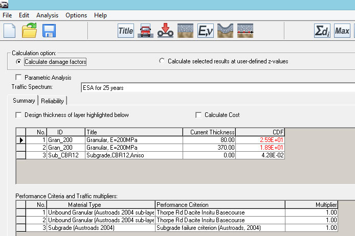
Repeating the analysis with a subgrade CBR of 12% closer to the scala measured
CBR of 13% results in the same short 1 year li e of the insitu Dacite aggregate as
shown below with a CDF of 25.9.
under the Official Information Act 1982
Released
Page 31 of 46
12.1.2 Pavement Renew al Design Report

under the Official Information Act 1982
Released
under the Official Information Act 1982
Released
Page 33 of 46
12.1.2 Pavement Renew al Design Report
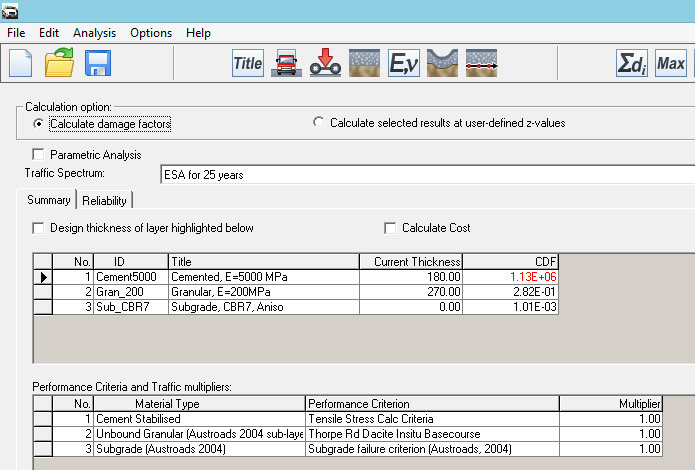
Tensile Stress Check for cracking
Thorpe Road Pavement Renewal Central Waikato NOC
Cemented, E=5000 MPa
Maximum damage values for each vehicle type
-------------------------------------------
Vehicle Type Damage Factor Critical Tensile Stress (MPa)
------------ ------------- ---------------
ESA750-Full .11278E+07 -0 81569E+00
Maximum of total damage= 1127803.
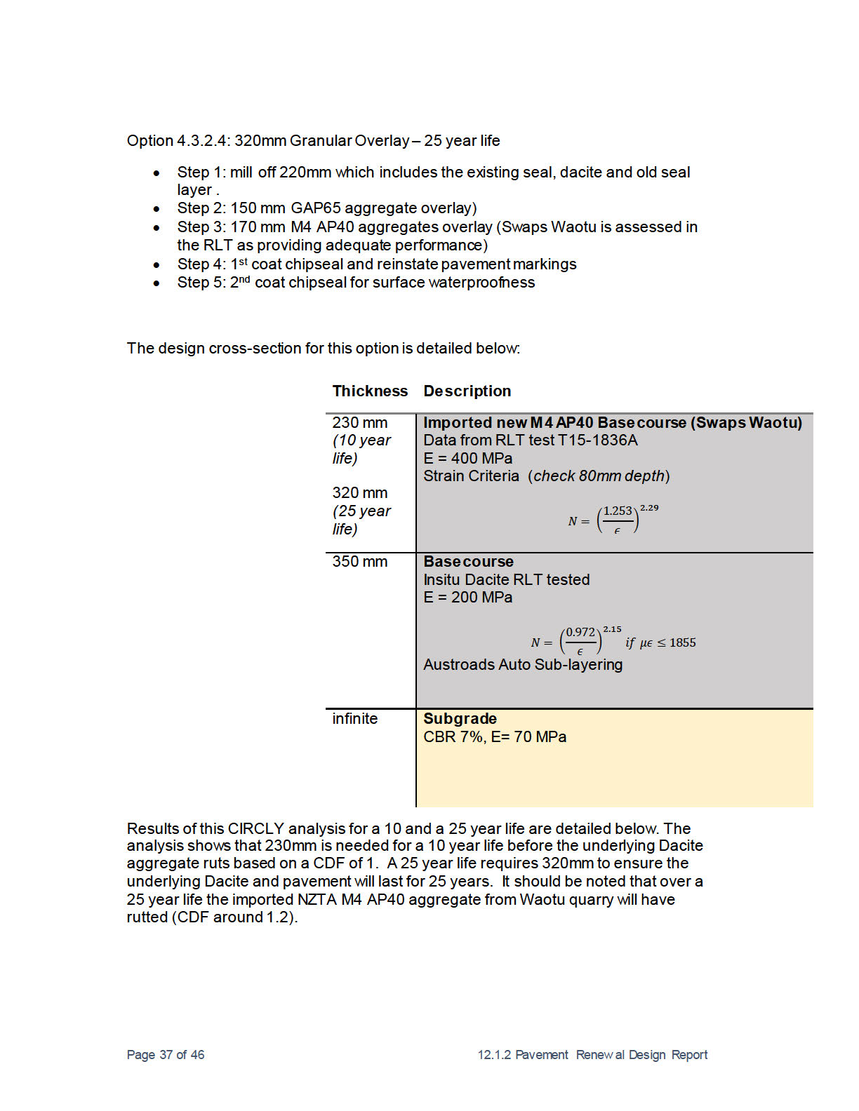
4.3.2.3
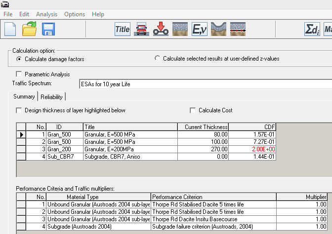
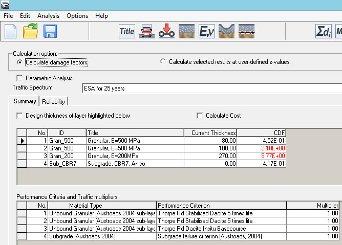
Option 3 – Remove 100mm seal layer and then 320mm M4 AP40
Granular Overlay
under the Official Information Act 1982
Option 3: 320mm Granular Overlay – 25 year life (230mm for 10 year life)
• Step 1: mill off 100mm existing seal.
• Step 2: 320 mm M4 granular overlay for a 25 year life or 230mm for a 10 year
life
• Step 3: 1st coat chipseal and reinstate pavement markings
• Step 4: 2nd coat chipseal for surface waterproofness
Released
The design cross-section for this option is detailed below:
Page 34 of 46
12.1.2 Pavement Renew al Design Report
under the Official Information Act 1982
Released
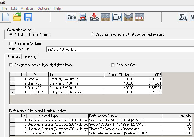
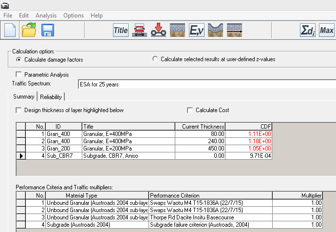
Figure – CIRCLY analysis 10 year life
under the Official Information Act 1982
Released
Figure – CIRCLY analysis 25 year life
Page 36 of 46
12.1.2 Pavement Renew al Design Report
under the Official Information Act 1982
Released
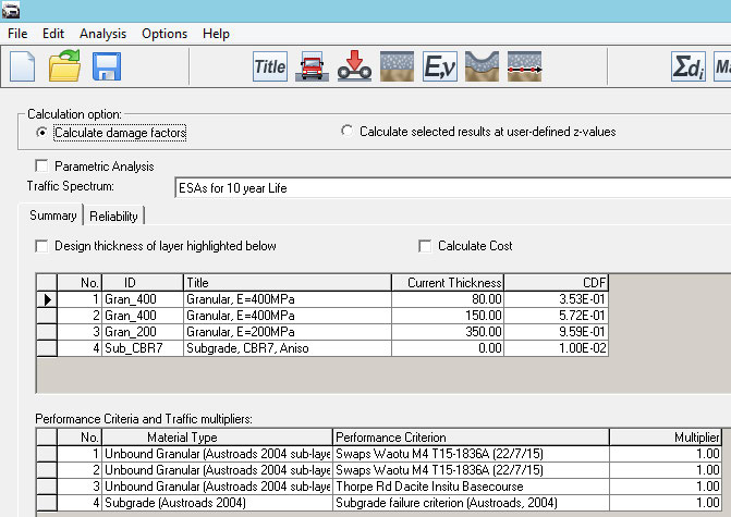
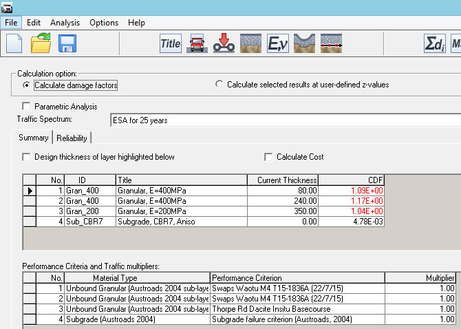
Figure – CIRCLY analysis for 10 year life
under the Official Information Act 1982
Released
Figure – CIRCLY analysis for 25 year life
Page 38 of 46
12.1.2 Pavement Renew al Design Report
4.3.3
Ancillary Pavement Works.
For construction, pavement needs an outward cross slope of 3.0% to ensure the
overlying seal can drain out to the shoulders of the road. Reshaping in areas may be
needed.
A deep subsoil drain is not needed, where pavement cross-section allows water to
daylight.
4.4
Geometrics
4.4.1
Design Standards
The standards used as the basis of the geometric design for this project are:
•
2005 NZTA Draft State Highway Geometric Design Manual (SHGDM)
•
2009 Austroads Guides to Road Design Part 3: Geometrics (AGRD03-10)]
4.4.2
Speed Environment
This site is located on an open and undulating section of SH 1 between Tokoroa and
Taupo. The site has an easy right hand curve with no speed restriction located just
south of the crossroad intersection with Thorpe Road. The speed environment for
this site is 100km/h.
4.4.3
Typical Section
The design cross section used is two 3.5m lanes with a minimum of 1.5m sealed
shoulders both sides. The sealed shoulders widen both sides at Thorpe Road
intersection to follow the existing edge of seal. Outside of the shoulders a 5:1 feather
edge leads to 1:1 fill slops to existing ground.
under the Official Information Act 1982
4.4.4
Horizontal Alignment Design
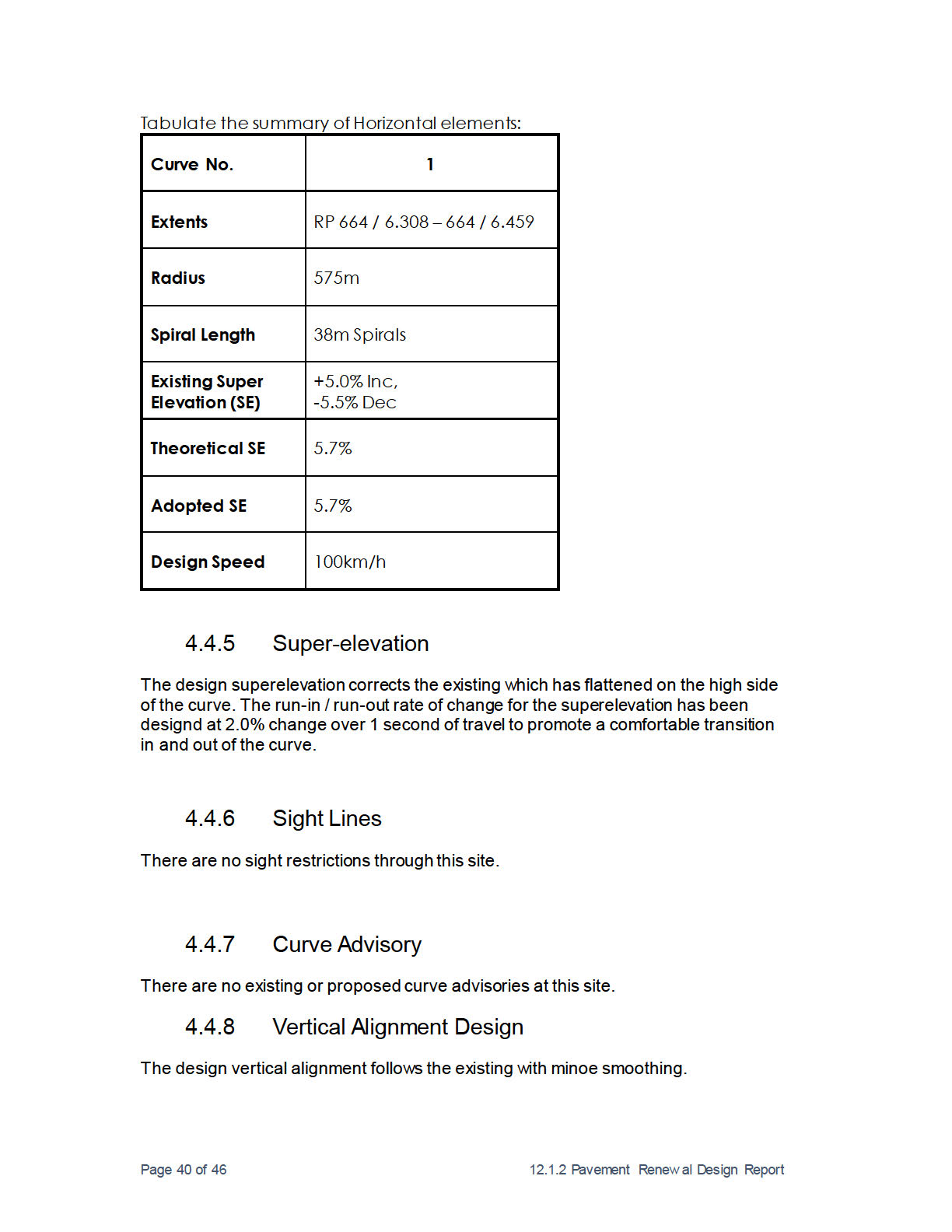
The horizontal alignment consists of two straights joined with a compound curve of
approximately 1:2:1 ratio (spiral to curve to spiral). See table below for details.
Released
Page 39 of 46
12.1.2 Pavement Renew al Design Report
under the Official Information Act 1982
Released
4.4.8.1
Sight Distance Criteria
The existing unrestricted site is unchanged.
4.4.9
Intersections
The existing crossroad intersection next to this site is unchanged.
4.4.10 Widening
There is no requirement for additional widening at this site.
4.4.11 Safety Improvements
• Document agreed safety improvements from the NZTA Safety Engineer to be
funded from Minor Safety funding. Reference Safety Assessment Form.
4.4.12 Safety Audit
As there are no significant geometric improvements in this project, a safety audit is
not required.
4.4.13 Additional Surfacing Requirement
Additional seal 0.5m wide has been added to the high side of the curve to reduce the
amount of water getting into the pavement through the unsealed feather edge.
4.5
Drainage
This pavement is well drained but consideration has be given to remove old seal
layers that trap water and prevent vertical downwards drainage of the granular
under the Official Information Act 1982
layers.
Released
Page 41 of 46
12.1.2 Pavement Renew al Design Report

List of
Appendices
Appendix A: Test Pits and Scalas
43
under the Official Information Act 1982
Released
Page 42 of 46
 Appendix A: Test Pits and Scala’s
under the Official Information Act 1982
Released
Page 43 of 46
 Appendix B: Material Testing
under the Official Information Act 1982
Released
Page 44 of 46